Capacitively coupled electric field control device

A capacitive coupling, electric field technology, used in instruments, optics, lenses, etc.

Active Publication Date: 2015-10-14
LENSVECTOR
View PDF10 Cites 6 Cited by
  • Summary
  • Abstract
  • Description
  • Claims
  • Application Information

AI Technical Summary

Problems solved by technology

[0018] Corresponding to the problems described above, it is necessary to develop another way to generate a non-uniform electric

Method used


Image

  • Capacitively coupled electric field control device
  • Capacitively coupled electric field control device
  • Capacitively coupled electric field control device

Examples


Embodiment Construction

[0080] Structure and operation of capacitive coupling optical device

[0081] The technical problems mentioned above can be solved by a different method based on capacitive coupling. Picture 10 The working principle of realizing this coupling is shown schematically. Two electrodes 901 / 902 arranged close enough to realize the voltage coupling are used, and a capacitance C is formed between the electrodes 901 / 902 (for example only)

[0082] C=ε r ε 0 A / d,

[0083] Where A is the area of ​​the overlapping area of ​​the two plates, ε r Is the static relative permittivity of the spacer material (also called "intermediate material") between the two plates, ε 0 Is the dielectric constant of the vacuum and d is the separation distance between the plates.

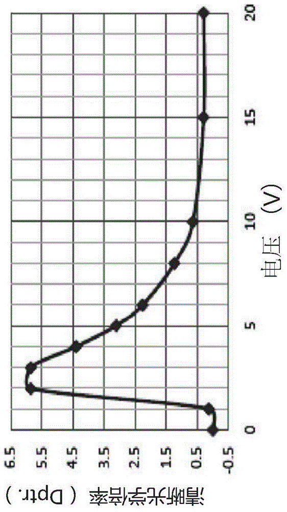
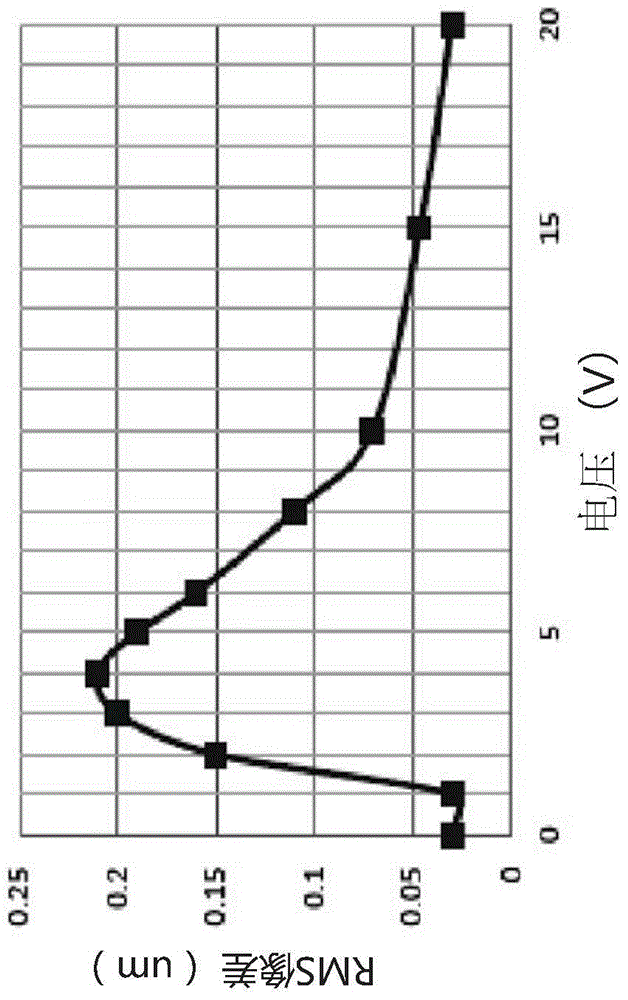
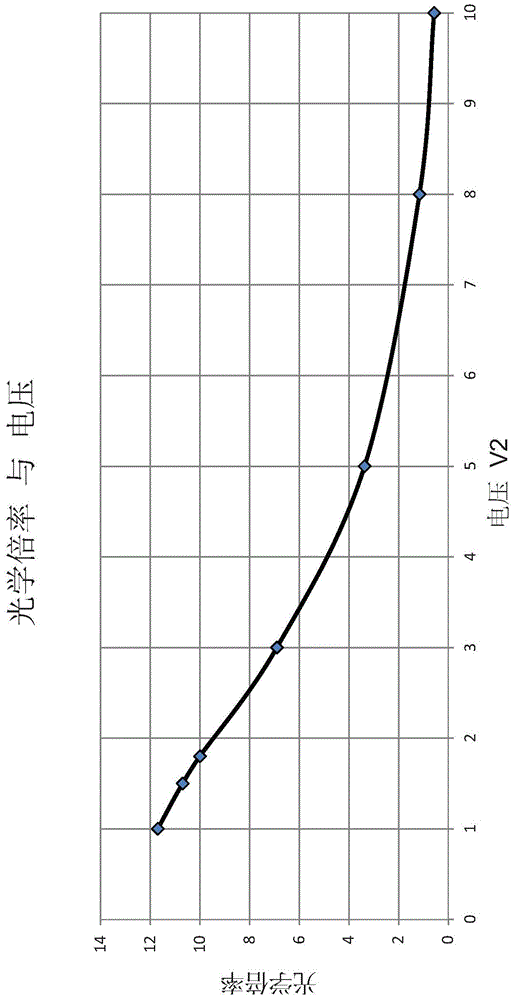
[0084] The solution proposed in this application is the coupling or transfer of the voltage from the electrically connected electrode 901 to another floating electrode 902. Experiments confirmed as Picture 11 As shown, two electrodes are...


PUM


Abstract

An electrode structure is proposed for controlling a spatially non-uniform electric field driving a tunable liquid crystal lens or beam steering device. The spatially non-uniform electrode structure enables the generation of a predetermined spatially non-uniform electric field profile where complex capacitive coupling between multiple different electrically floating neighboring electrode segments is employed for the generation of the electrical field of desired form by supplying an initial electric potential to a limited number of electrodes.

Description

[0001] Related application [0002] The priority document of this application is the U.S. Provisional Application US 61 / 725,021, the title of which is the same as this application, and the filing date is November 11, 2012. This application quotes the full text of the priority document. Technical field [0003] The technical solution of the present application relates to a liquid crystal optical device, particularly a control electrode of a liquid crystal optical device. Background technique [0004] Liquid crystal (LC) displays (LCD) and liquid crystal lenses (LCL) are known in the art. In most cases where liquid crystals are used, an electrically variable gradient refractive index (called GRIN) optical lens is formed, and the relative orientation gradient of the liquid crystal molecules in the space in the light through hole (Clear Aperture, CA) of the control device is formed. Control the lens. The orientation of the liquid crystal molecules is sensitive to the electric field, a...

Claims


Application Information

Patent Timeline
IPC IPC(8): G02B1/00G02B3/12G02B5/00G02F1/13
CPCG02F1/29G02F2001/294G02F2201/128G02F1/294G02B27/646G02F1/13306G02F1/133345G02F1/134309G02F1/13471G02F1/134354
Inventor 迪格兰·加尔斯蒂安弗拉底米尔·普雷尼亚科夫卡伦·阿萨特里安阿米尔·图尔克阿尔门·佐哈拉拜亚恩阿拉姆·巴格拉姆亚恩西蒙·卡洛
Owner LENSVECTOR
Why Eureka
Try Eureka