Shaker

A vibrating screen and screen box technology, which is applied in the fields of filtration, solid separation, chemical instruments and methods, etc., can solve the problems of uneven distribution of minerals, low screening efficiency, and easy wear of the screen, so as to prolong the service life and reduce friction , the effect of slowing down wear

Active Publication Date: 2017-10-03
柳州华锡有色设计研究院有限责任公司
View PDF13 Cites 0 Cited by
  • Summary
  • Abstract
  • Description
  • Claims
  • Application Information

AI Technical Summary

Problems solved by technology

[0003] The technical problem to be solved by the present invention is to provide a vibrating screen to solve the problems of uneven distribution of minerals on the screen, low screening efficiency, and easy wear of the mounting bolts of the vibrating motor and the screen below the vibrating motor

Method used


Image

  • Shaker
  • Shaker
  • Shaker

Examples


Embodiment 1

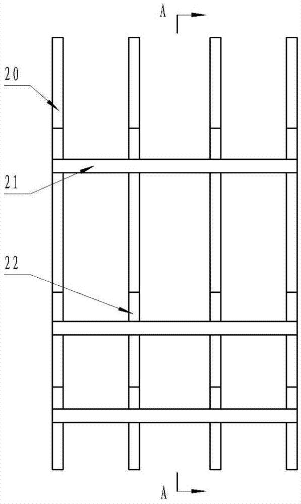
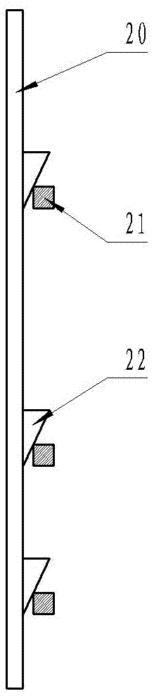
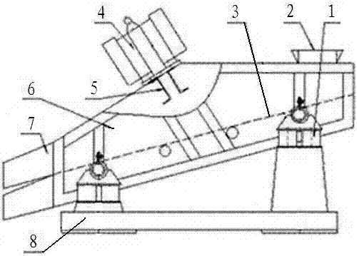
[0018] Such as image 3 , Figure 4 The shown vibrating screen includes a screen box 6 with a feed inlet 2 and a discharge outlet 7. The screen box 6 is obliquely installed on the bracket 8 through the damping spring 1, and the middle top position of the screen box 6 is equipped with Motor pedestal 5, two vibrating motors 4 are fixed on the motor pedestal 5 through mounting bolts, two layers of screen 3 are installed in the screen box 6 through the screen frame, and two long layering strips parallel to the material conveying direction are installed on the screen 3 10. Above the two long layering bars 10, there are three spaced horizontal pressing bars 11 fixed on both sides of the screen box 6, and four short layering bars 9 are installed between the two long layering bars 10, and the two short layering bars 9 are arranged along the material The conveying direction is arranged at intervals, and the distance between the two short layering bars 9 arranged at intervals along the...

Embodiment 2

[0021] The difference between this embodiment and Embodiment 1 is that the distance between the two short bead 9 arranged at intervals along the material conveying direction is 350 millimeters; The distance L is 150 mm. All the other features are the same as in Example 1.


PUM


Abstract

The invention discloses a vibrating screen and relates to the technical field of ore dressing machinery. The vibrating screen comprises a screen box provided with a feed port and a discharge port. The screen box is internally provided with a plurality of layers of screen bodies through screen frames. Two long pressing bars parallel to the material conveying direction are mounted on the screen bodies. A plurality of transverse pressure levers fixed to the two sides of the screen box are mounted above the long pressing bars. A plurality of short pressing bars arranged in the material conveying direction at intervals are mounted between the two long pressing bars. The upper end of the short pressing bar close to the feed port is lower than the upper ends of the long pressing bars. Wedge blocks are mounted between the transverse pressure levers and the long pressing bars and between the transverse pressure levers and the short pressing bars. Compared with the prior art, the vibrating screen can make minerals evenly distributed on the screen bodies, and the screening efficiency reaches 90% or higher; the service life of mounting bolts of a vibrating motor and the service life of the screen bodies below the vibrating motor are prolonged.

Description

technical field [0001] The invention relates to the technical field of mineral processing machinery, in particular to a vibrating screen for mineral processing. Background technique [0002] The vibrating screen is a commonly used screening machine in mineral processing plants, and the linear vibrating screen is more widely used. It uses the vibration of the vibrating motor as the vibration source to make the material be thrown on the screen and move forward in a straight line at the same time. The material is evenly distributed from the feeder. It enters the feed inlet of the screening machine, and produces several specifications of oversize and undersize through the multi-layer screen, which are respectively discharged from their respective outlets. A kind of vibrating screen currently used, the vibrating screen includes a screen box with a material inlet and a material outlet, the screen box is installed obliquely on the bracket through a damping spring, and a motor pedes...

Claims


Application Information

Patent Timeline
Patent Type & Authority Patents(China)
IPC IPC(8): B07B1/28B07B1/46
CPCB07B1/28B07B1/46
Inventor 陈志文梁增永赖锦尚欧阳发吴传坤黄艳朱文涛唐川
Owner 柳州华锡有色设计研究院有限责任公司
Why Eureka
Try Eureka