Rear assembled engine foot

An assembly type, engine technology, applied in the field of automobile engine feet, can solve the problems of complex vulcanization mold processing, high product development cost, waste of resources and costs, etc., and achieve the effect of shortening the processing cycle, simple and reasonable structure, and saving resources and costs.

Inactive Publication Date: 2015-10-21
ANHUI ZHONGDING NVH
View PDF3 Cites 0 Cited by
  • Summary
  • Abstract
  • Description
  • Claims
  • Application Information

AI Technical Summary

Problems solved by technology

[0002] In the current field, the design of the rear engine feet used in automobiles is generally an integral process that vulcanizes rubber, brackets and covers together. The vulcanization mold processing is complicated, the processing c

Method used


Image

  • Rear assembled engine foot
  • Rear assembled engine foot

Examples


Embodiment Construction

[0009] In order to make the object, technical solution and advantages of the present invention clearer, the present invention will be further described in detail below in conjunction with the accompanying drawings and embodiments. It should be understood that the specific embodiments described here are only used to explain the present invention, not to limit the present invention.

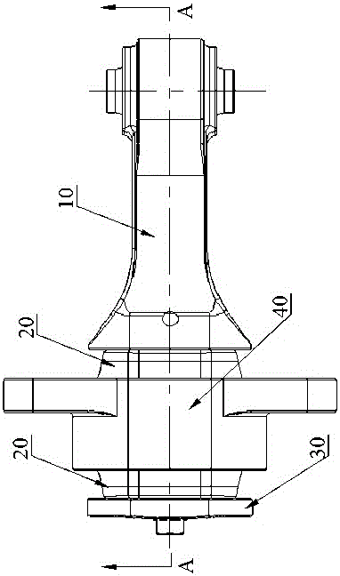
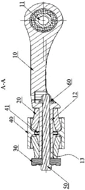
[0010] see figure 1 and figure 2 ,in figure 1 It is a structural schematic diagram of an assembled rear engine foot of the present invention; figure 2 for figure 1 A-A in the sectional view.

[0011] The assembled rear engine foot includes a bracket 10, two rubber sleeves 20, a baffle plate 30, an outer cover 40, bolts 50 and nuts 60, and one end of the bracket 10 is provided with a connecting shaft hole 11, and the connecting shaft hole 11 The central axis of the support 10 is perpendicular to the support 10, the other end of the support 10 is provided with a support rod 12, the central axi...


PUM


Abstract

The invention relates to a rear assembled engine foot. The rear assembled engine foot comprises a bracket, two rubber sleeves, a baffle, an outer shell, a bolt and a nut, wherein a connection rotating shaft hole is formed in one end of the bracket, and the central axis of the connection rotating shaft hole is perpendicular to the bracket; a supporting rod is arranged at the other end of the bracket, and a through hole is formed on the central axis of the supporting rod; each rubber sleeve adopts a trumpet-shaped tubular structure; the outer shell is in a cylinder shape; a plate propping ring is arranged on the inner wall of the outer shell and positioned at the middle part of the outer shell, and the plate propping ring and the outer shell are coaxial; the outer shell sleeves the periphery of the supporting rod, and the outer shell and the supporting rod are coaxial; the two rubber sleeves are respectively arranged on both sides of the outer shell; the rubber sleeves sleeve the periphery of the supporting rod, and one side with a large caliber, of each rubber sleeve, is tightly attached to the plate propping ring on the outer shell; the baffle is propped against one side with a small caliber, of the rubber sleeve which is far away from the connection rotating shaft hole, and the small caliber of the rubber sleeve on one side which is close to the connection rotating shaft hole is propped against the bracket; the bolt sequentially penetrates through the through hole in the baffle and the through hole in the supporting rod and is fastened with the nut.

Description

technical field [0001] The invention relates to the technical field of automobile engine feet, in particular to an assembled rear engine foot. Background technique [0002] In the current field, the design of the rear engine feet used in automobiles is generally an integral process that vulcanizes rubber, brackets and covers together. The vulcanization mold processing is complicated, the processing cycle is long, the product development cost is high, and the number of shifts is small. Especially After this kind of engine foot is damaged, it must be replaced with a new engine foot as a whole, thereby wasting a lot of resources and costs. Contents of the invention [0003] In view of this, it is necessary to provide an assembled rear engine foot with simple processing, short cycle time, low cost, improved production efficiency, and saved a lot of resource costs. [0004] The present invention is realized in this way, an assembled rear engine foot includes a bracket, two rub...

Claims


Application Information

Patent Timeline
IPC IPC(8): B60K5/12
Inventor 何仕生彭建芳曹德文沈轶储葵
Owner ANHUI ZHONGDING NVH
Why Eureka
Try Eureka