A vector propulsion device, an airship and an installation method of the vector propulsion device

A technology of vector propulsion and installation method, which is applied in the direction of rigid spaceships, etc. It can solve the problems of increasing the size of the pod, rolling, and the weight of the pod structure, etc., and achieves the effects of convenient lashing operation, high lashing quality, and large load capacity

Active Publication Date: 2017-06-16
ACAD OF OPTO ELECTRONICS CHINESE ACAD OF SCI
View PDF2 Cites 0 Cited by
  • Summary
  • Abstract
  • Description
  • Claims
  • Application Information

AI Technical Summary

Problems solved by technology

The motor is powered by a lithium battery, and the speed and steering are adjusted by the radio receiver and electronic regulator. It is controlled by a radio remote control transmitter placed in the hanging basket or on the ground, and the blades of the propeller rotate to generate thrust. Such a structure The disadvantages are: as the diameter of the propeller increases, the size of the pod will be greatly increased, and the structural form of the pod will become complicated, and the structural weight of the pod will increase significantly, so that the pod will cause damage to the hull. severe stress concentration
[0005] Another example is the Chinese invention patent "A New Type of Airship" with application number 200720173979.8, which discloses an aircraft with good maneuverability, including a hull, a car, a propeller, a control system, and a landing gear. The hull is a spindle wing Shaped, at least two propellers are arranged symmetrically on both sides of the hull, and two small airbags for adjusting buoyancy and weight are arranged in the hull. Far, causing the thrust generated by the propulsion device to affect the angle of attack of the hull, which brings problems to the real-time control of the attitude of the hull
At the same time, when relying on the propellers on both sides to differentially yaw, because the force arm between the thrust and the hull axis is small, the differential torque generated by the propellers on both sides is less effective in controlling yaw.
[0006] In addition, in the existing installation method of the propeller and the hull, when installing the propellers on both sides of the hull, especially the propellers with large size and heavy weight, if the synchronous installation cannot be guaranteed, the weight of the propulsion device will have an impact on the axis of the hull. Due to the action of the torque, the hull will roll to the side where the propulsion device is installed first, so that it will affect the subsequent installation

Method used


Image

  • A vector propulsion device, an airship and an installation method of the vector propulsion device
  • A vector propulsion device, an airship and an installation method of the vector propulsion device
  • A vector propulsion device, an airship and an installation method of the vector propulsion device

Examples


Embodiment 1

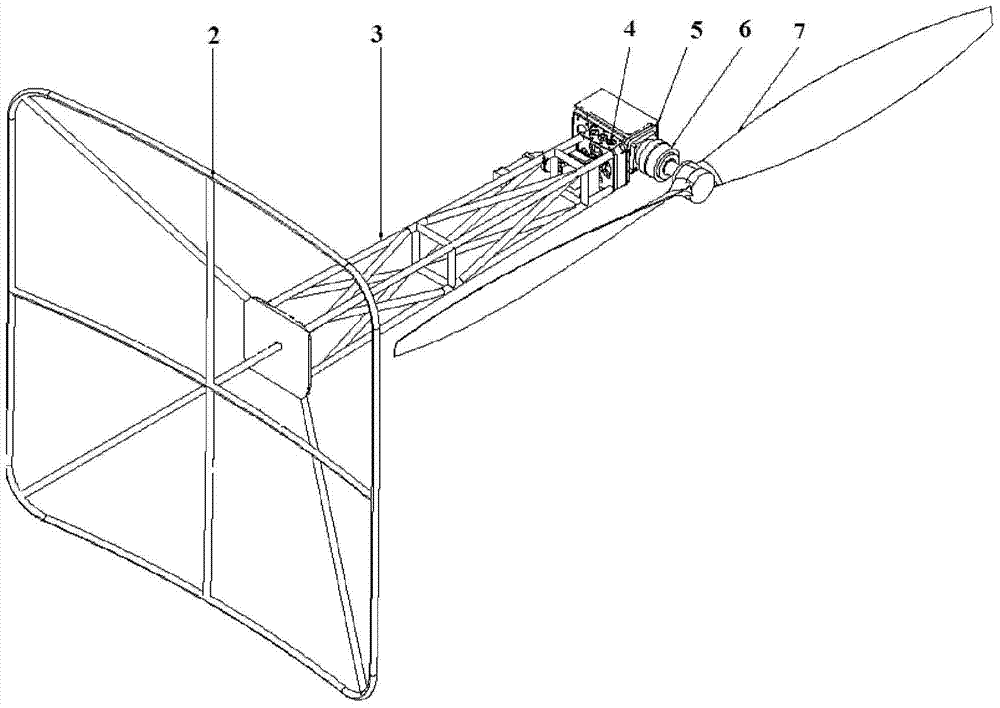
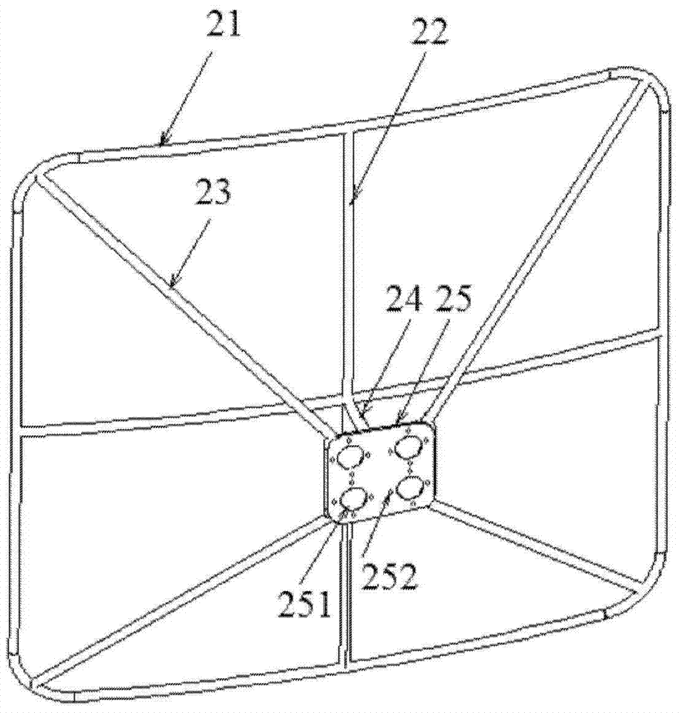
[0044] like Figure 1 to Figure 3 As shown, the vector propulsion device of this embodiment includes a driving device, the driving device in this embodiment is a power motor 5, the driving device is connected with a propeller 7, the driving device is connected with a transition frame 2, and the curvature at the bottom of the transition frame 2 is the same as that of the hull The curvature of the side part is used to install the transition frame 2. Specifically, after the hull is inflated, the overall shape is roughly ellipsoidal. The curvature of the bottom of the transition frame 2 in this embodiment is used to install the transition frame on the side of the hull. The curvatures of the 2 parts are compatible, that is, in this embodiment, the bottom of the transition frame 2 is set as a roughly concave arc-shaped matching surface that matches the side of the hull,

[0045] Specifically, the bottom of the transition frame 2 in this embodiment is a "Tian"-shaped frame, the frame...

Embodiment 2

[0063] like Figure 1 to Figure 5 As shown, this embodiment includes a kind of airship, including a hull. The hull is ellipsoidal after being inflated. Both sides of the hull are respectively provided with a vector propulsion device. The structure of the vector propulsion device in this embodiment is as in Embodiment 1. , the connection between the hull and the vector propulsion device is located at the largest diameter on both sides of the hull. By setting the vector propulsion device at the largest diameter on both sides of the hull, the size and concentrated weight of the pod can be significantly reduced, and the impact of thrust changes on the hull can be reduced. The influence of the pitch angle, and through the difference in the speed of the power motors on both sides, a greater yaw moment is obtained, thereby improving the maneuverability of the airship.

Embodiment 3

[0065] The vector propulsion device of the present invention is installed on both sides of the airship hull, and is tied to the specified position at the maximum diameter of both sides of the hull 1 through the mirror image of the transition frame 22. In order to clearly express the embodiment of the present invention, only two sets of vector The implementation of the propulsion device is described as an example. The implementation of more than 2 sets of vector propulsion devices is exactly the same as the implementation of 2 sets of vector propulsion devices. It is only necessary to increase the number of vector propulsion devices. When describing the assembly process of the vector propulsion device, one set of vector propulsion device is selected for illustration, and the assembly steps of each set are the same.

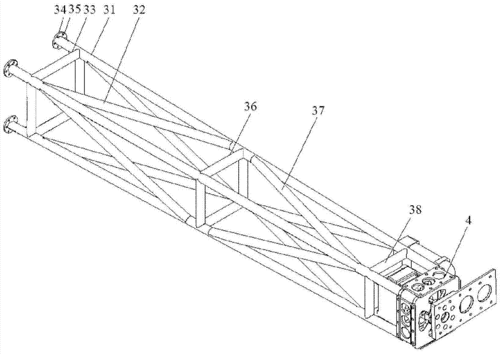
[0066] see figure 1 The structure of the vector propulsion device of the present invention is shown, including: a transition frame 2 , a propulsion bracket 3 , a t...


PUM


Abstract

The invention relates to a vector propulsion device, an airship and an installation method of the vector propulsion device. The vector propulsion device includes a drive device, the drive device is connected with a propeller, the drive device is connected with a transition frame, and the bottom of the transition frame is The curvature of the hull is adapted to the curvature of the side of the hull for installing the transition frame, the bottom of the transition frame can be tied and fixed with the side of the hull, the top of the transition frame is provided with a propulsion bracket, and the propulsion bracket The outer dimension is smaller than that of the bottom of the transition frame, and the driving device is arranged on the propulsion support. With such a structure, the entire propulsion device is stably connected to the hull through the bottom frame whose shape and curvature are adapted to the side of the hull, and the transition frame as a whole has a large bottom and small top space structure, with good connection stability , and can increase the distance between the tip of the propeller and the hull, reduce the aerodynamic imbalance during the rotation of the propeller, and reduce the interference of the aerodynamic force of the propeller on the hull.

Description

technical field [0001] The invention relates to the technical field of airship propulsion, in particular to a vector propulsion device, an airship and a method for installing the vector propulsion device. Background technique [0002] In recent years, with the improvement of environmental protection awareness, the improvement of electric propulsion technology and the arrival of the upsurge of research on airships flying at stratospheric altitudes, electric airships have become a hot spot in current airship research. The flying speed of the electric airship is relatively low. In order to improve the maneuverability of the airship at low speed, the propulsion device with a tilting device is generally used in the design of the airship. Traditional vector propulsion devices are generally installed on both sides of the pod, and the tilting device is placed in the pod. The stepping motor drives the belt, gear or chain to drive the tilting shaft to realize the synchronous tilting o...

Claims


Application Information

Patent Timeline
Patent Type & Authority Patents(China)
IPC IPC(8): B64B1/32
Inventor 聂营杨燕初王旭巍祝榕辰李兆杰张衍垒
Owner ACAD OF OPTO ELECTRONICS CHINESE ACAD OF SCI
Why Eureka
Try Eureka