System and method for energy cascade utilization of small steam turbines in thermal power plants

A technology for small steam turbines and thermal power plants, applied in steam engine installations, mechanical equipment, machines/engines, etc., can solve the problems of difficulty in fully utilizing steam energy, high requirements for the design and manufacture of supporting main steam turbines and safe operation, and is easy to popularize and apply. , Reduce the requirements for design and manufacture and safe operation, the effect of simple structure

Active Publication Date: 2016-10-26
HUADIAN ELECTRIC POWER SCI INST CO LTD
View PDF9 Cites 0 Cited by
  • Summary
  • Abstract
  • Description
  • Claims
  • Application Information

AI Technical Summary

Problems solved by technology

The above-mentioned technical features of the present invention form an inseparable whole, and the above-mentioned technical features of the present invention cannot be completely divided into several parts to be viewed. The design, manufacture and safe operation of the steam turbine have high requirements, and the large amount of steam energy driving the small steam turbine of the feed water pump is difficult to be fully utilized, and the overall structure is simple, which is convenient for promotion and application

Method used


Image

  • System and method for energy cascade utilization of small steam turbines in thermal power plants
  • System and method for energy cascade utilization of small steam turbines in thermal power plants

Examples


Embodiment 1

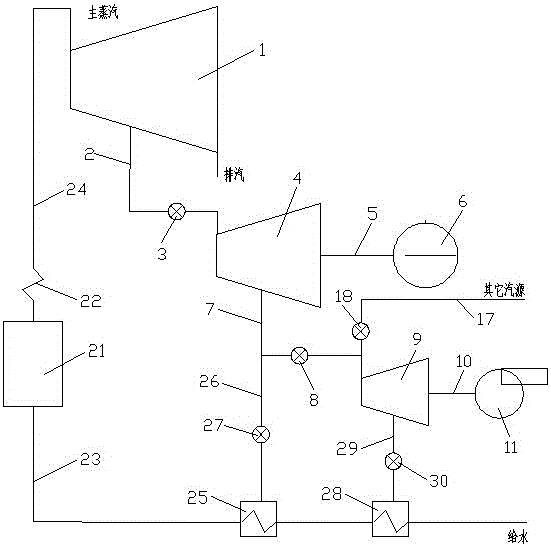
[0017] see figure 1 , the thermal power plant small steam turbine energy cascade utilization system in the present embodiment consists of a main steam turbine 1, a main steam inlet pipe 2, a main steam inlet regulating valve 3, a small steam turbine for driving a feedwater pump 4, a feedwater pump connecting shaft 5, a feedwater pump 6, a No. 1 steam inlet pipe 7, No. 1 regulating valve 8, No. 1 driving induced draft fan small steam turbine 9, No. 1 induced draft fan connecting shaft 10, No. 1 induced draft fan 11, No. 1 other air source steam inlet pipe 17, No. 1 other air source Steam inlet pipe regulating valve 18, boiler 21, evaporator 22, water supply pipe 23, main steam pipe 24, high pressure heater 25, high pressure heating pipe 26, No. 3 regulating valve 27, low pressure heater 28, No. 1 low pressure heating pipe 29 And No. 4 regulating valve 30 forms.

[0018] In this embodiment, one end of the main steam pipe 24 is connected to the evaporator 22, the other end of th...

Embodiment 2

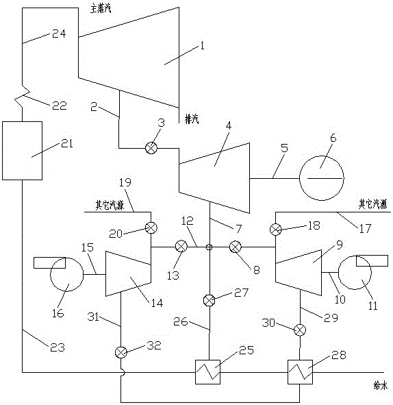
[0025] see figure 2 , the thermal power plant small steam turbine energy cascade utilization system in the present embodiment consists of a main steam turbine 1, a main steam inlet pipe 2, a main steam inlet regulating valve 3, a small steam turbine for driving a feedwater pump 4, a feedwater pump connecting shaft 5, a feedwater pump 6, a No. 1 steam inlet pipe 7, No. 1 regulating valve 8, No. 1 driving induced draft fan small steam turbine 9, No. 1 induced draft fan connecting shaft 10, No. 1 induced draft fan 11, No. 2 steam inlet pipe 12, No. 2 regulating valve 13, No. 2 Drive induced draft fan small steam turbine 14, No. 2 induced draft fan connecting shaft 15, No. 2 induced draft fan 16, No. 1 other air source inlet pipe 17, No. 1 other air source inlet pipe regulating valve 18, No. 2 other air source inlet steam Pipe 19, No. 2 other gas source inlet pipe regulating valve 20, boiler 21, evaporator 22, water supply pipe 23, main steam pipe 24, high-pressure heater 25, hig...

Embodiment 3

[0036] see figure 1 and figure 2 , the steps of the energy cascade utilization method of the small steam turbine in the thermal power plant in the present embodiment are: the main steam generated in the evaporator 22 enters the main steam turbine 1 along the main steam pipe 24, and the main steam turbine 1 only directly provides steam to the small steam turbine 4 for driving the feed pump, After the pressure and temperature parameters of the small steam turbine 4 driving the feed pump have been worked, part of the steam is directly pumped to the small steam turbine of the induced draft fan to drive the small steam turbine of the induced fan to do work, and the steam that has done the work of the small steam turbine of the induced fan is then drawn to the low-pressure heater 28 to heat the feed water in the water supply pipe 23, and another part of the steam is pumped to the high-pressure heater 25 to heat the feed water in the water supply pipe 23, so that the heat of the ste...


PUM


Abstract

The invention relates to an energy gradient utilization system and method for a small turbine of a thermal power plant. Currently, steam feed pump systems and steam induced draft fan systems have many defects. The system comprises a main steam turbine, a main steam feeding pipe, a main steam feeding regulation valve, a feed pump drive small turbine, a feed pump connection shaft and a feed pump. The system is characterized by further comprising a first steam feeding pipe, a first regulation valve, a first induced draft fan drive small steam turbine, a first induced draft fan connection shaft and a first induced draft fan, wherein one end of the first steam feeding pipe is connected to the feed pump drive small turbine, the other end of the first steam feeding pipe is connected to the first induced draft fan drive small steam turbine, and the first regulation valve is arranged on the first steam feeding pipe. The method comprises the steps that the main steam turbine only provides steam for the feed pump drive small turbine directly, and then a part of steam obtained after acting in the feed pump drive small turbine is directly pumped to the induced draft fan drive small steam turbine to drive the small turbine to act. The energy gradient utilization system and method can conveniently and effectively achieve energy gradient utilization.

Description

technical field [0001] The invention relates to an energy cascade utilization system and method, in particular to an energy cascade utilization system and method for a small steam turbine in a thermal power plant, which can rationally arrange the steam system of the small steam turbine so as to achieve high energy utilization. Background technique [0002] At present, most of the feed water pumps and induced draft fans for generating sets in thermal power plants are driven by electric motors, and some are driven by small steam turbines. Electric motor-driven feed water pumps and induced draft fans, whose electric energy comes from the substation electricity of the thermal power plant, this method increases the substation electricity consumption and reduces the on-grid electricity consumption. The use of small steam turbines to drive feed water pumps and induced draft fans can effectively reduce the power consumption rate of thermal power plants, reduce power generation costs...

Claims


Application Information

Patent Timeline
Patent Type & Authority Patents(China)
IPC IPC(8): F01K7/02F01K7/16F01K7/38F01K13/00F01D15/08
Inventor 张海珍宋华伟何胜郑文广袁伟宋国亮张鑫
Owner HUADIAN ELECTRIC POWER SCI INST CO LTD
Why Eureka
Try Eureka