
A cascaded energy utilization system and method for small steam turbines in a thermal power plant

A technology of small steam turbines and thermal power plants, applied in the field of energy cascade utilization systems, can solve problems such as the complexity of energy cascade utilization systems, and achieve the effects of easy promotion and application, easy transformation, and simple structure

Active Publication Date: 2018-04-24
HUADIAN ELECTRIC POWER SCI INST CO LTD
View PDF8 Cites 0 Cited by
  • Summary
  • Abstract
  • Description
  • Claims
  • Application Information

AI Technical Summary

Problems solved by technology

Of course, there are also relatively good energy cascade utilization systems and methods for small steam turbines in thermal power plants that can realize energy cascade utilization. A system and method for energy cascade utilization of small steam turbines in a power plant. Although the main steam turbine in the energy cascade utilization method of small steam turbines in a thermal power plant only directly provides steam to the small steam turbines that drive the feedwater pumps, the steam that has been partially worked in the small steam turbines that drive the feedwater pumps is directly pumped. To the small steam turbine of the induced draft fan to drive the small steam turbine to do work, but the energy cascade utilization system of the small steam turbine in the thermal power plant is relatively complicated
[0005] At present, there is no energy cascade utilization system and method for small steam turbines in thermal power plants with simple structure, which can effectively reduce the power generation cost of thermal power plants, save energy, and indirectly reduce emissions.

Method used


Image

  • A cascaded energy utilization system and method for small steam turbines in a thermal power plant

Examples


Embodiment Construction

[0020] The present invention will be further described in detail below in conjunction with the accompanying drawings and examples. The following examples are explanations of the present invention and the present invention is not limited to the following examples.

[0021] Example.

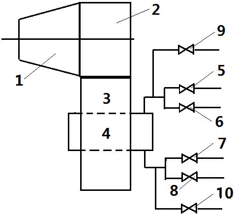
[0022] see figure 1 , the thermal power plant small steam turbine energy cascade utilization system in this embodiment includes a small steam turbine 1 for a feed water pump, an exhaust pipe 3 for a small steam turbine for a feed water pump, a small heat network heater 4, a small heat network heater condensate side outlet valve 5, a small Heat network heater heat network circulating water side outlet valve 6, small heat network heater condensate water side inlet valve 7, small heat network heater heat network circulating water side inlet valve 8, small heat network heater condensate replenishment water inlet for water quality cleaning Valve 9 and small heating network heater condense make-up water...


PUM


Abstract

The invention relates to a cascaded energy utilization system and method for small steam turbines in a thermal power plant. At present, there is no such system and method for saving energy and indirectly reducing emissions. The system of the present invention includes a small steam turbine of the feed water pump, an exhaust pipe of the small steam turbine of the feed water pump, and a small heat network heater, and is characterized in that it also includes a switching valve group for the circulating water of the condensate heating network, and the switching valve group for the circulating water of the condensate heating network passes through The pipeline is connected to a small heating network heater. The method of the present invention is as follows: during the heating period of the heating network, the high-temperature exhaust gas of the small steam turbine of the feedwater pump passes through the small heating network heater to preheat the circulating water of the heating network; during the non-heating period, the high-temperature exhaust gas of the small steam turbine of the feedwater pump passes through the small heating network The heater preheats the condensed water, and the high-temperature exhaust gas from the small steam turbine of the feed water pump passes through the small heat network heater, and the condensed water flows to the condenser through the slope of the exhaust pipe of the small steam turbine of the feed water pump. The invention has a simple structure, saves energy and indirectly reduces emissions.

Description

technical field [0001] The invention relates to an energy cascade utilization system and method thereof, in particular to an energy cascade utilization system and method of a small steam turbine in a thermal power plant, which can rationally utilize the exhaust enthalpy drop of the small steam turbine, thereby achieving the purpose of efficient utilization of energy. Background technique [0002] The "Suggestions of the Central Committee of the Communist Party of China on Formulating the Thirteenth Five-Year Plan for National Economic and Social Development" adopted by the Fifth Plenary Session of the Eighteenth Central Committee of the Communist Party of China unprecedentedly positioned "green" and "innovation, coordination, openness, and sharing" as "development Concept", as one of my country's five major development ideas, development directions, and development focus points in the "13th Five-Year Plan" and even a longer period, runs through all fields and links of the "13t...

Claims


Application Information

Patent Timeline
Patent Type & Authority Patents(China)
IPC IPC(8): F01K7/38F01K17/02F24D3/00
CPCY02E20/14
Inventor 张士龙赵玉柱邹晓辉徐厚达郭佳雷庞乐邴汉昆
Owner HUADIAN ELECTRIC POWER SCI INST CO LTD
Learn More