Display lamp panel and splicing method thereof

A display screen and light board technology, applied in the field of display screens, can solve the problems of complex removal process and affecting visual effects

Active Publication Date: 2020-09-04
SHENZHEN AOTO ELECTRONICS
View PDF9 Cites 0 Cited by
  • Summary
  • Abstract
  • Description
  • Claims
  • Application Information

AI Technical Summary

Problems solved by technology

[0005] The purpose of the present invention is to provide a display lamp panel, aiming at removing the problems of complex process and gaps during splicing that affect the visual effect of the existing display lamp panel process

Method used


Image

  • Display lamp panel and splicing method thereof
  • Display lamp panel and splicing method thereof
  • Display lamp panel and splicing method thereof

Examples


Embodiment Construction

[0033] In order to make the objectives, technical solutions, and advantages of the present invention clearer, the following further describes the present invention in detail with reference to the accompanying drawings and embodiments. It should be understood that the specific embodiments described herein are only used to explain the present invention, but not to limit the present invention.

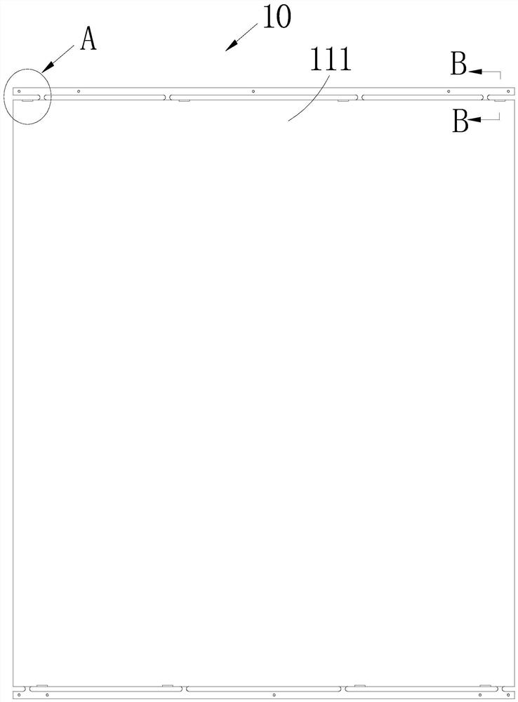
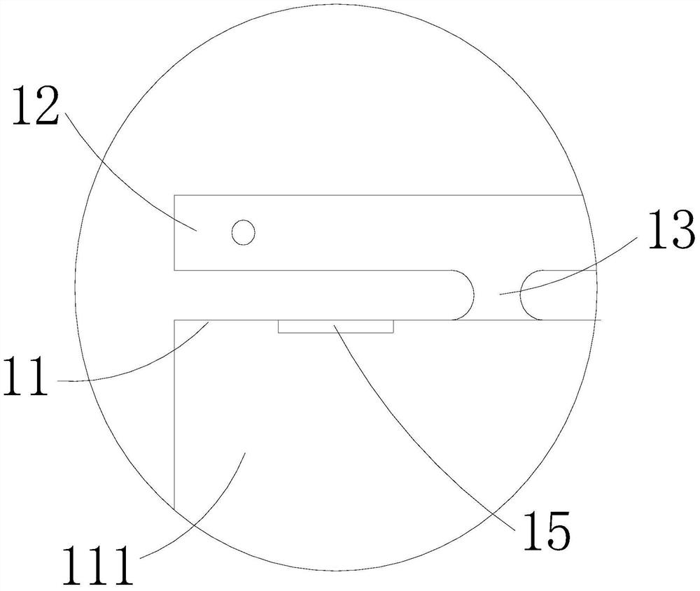
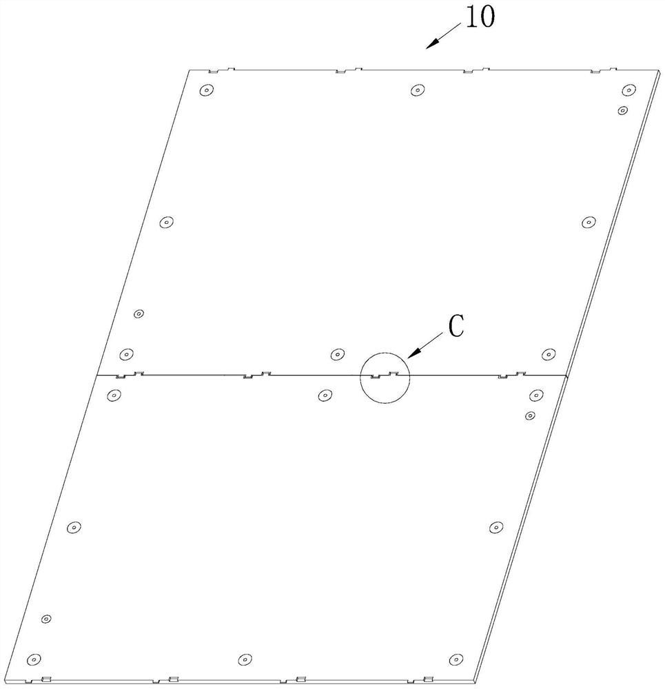
[0034] Such as Figure 1~7 Shown are the preferred embodiments provided by the present invention.

[0035] It should be noted that when a component is referred to as being "fixed to" or "installed on" another component, it can be directly on the other component or there may be a centering component at the same time. When a component is said to be "connected to" another component, it can be directly connected to the other component or a central component may also be present.

[0036] It should also be noted that the orientation terms such as left, right, up, and down in this embodiment are only ...


PUM


Abstract

The invention relates to the field of display screen technology, and provides a display screen lamp panel, comprising a panel. Two opposite side surfaces of the panel are connected with technical edges used to transmit the panel. The technical edges are connected with side surfaces through bridges. The two side surfaces are respectively provided with grooves used to match with burrs which are left after the bridges are cut off on the side surfaces. The bridges on a side surface are symmetrically arranged with the grooves on the other side surface. When a bridge is arranged on the same side surface, a groove is arranged at equal interval. The invention also provides a splicing method for the display screen lamp panels. The method comprises: processing technical edges on two opposite side surfaces of the display screen lamp panel, through processing the bridges, connecting the side surfaces with the technical edges; cutting off the bridges from the side surfaces; processing grooves on the two side surfaces, on a same side surface, when a bridge is processed, processing a groove at equal interval, on different side surfaces, the bridges and the grooves being processed symmetrically; and aligning the burrs on a side surface at the grooves on the other side surface, to perform splicing cooperation of two display screen lamp panels.

Description

Technical field [0001] The invention belongs to the field of display screen technology, and particularly relates to a display screen lamp panel and a splicing method thereof. Background technique [0002] At present, most of the production of PCB boards adopts automated operations to meet the requirements of large-volume, high-efficiency production. Automation equipment, such as solder paste printers, glue dispensers, placement machines, reflow soldering, etc., uses track transmission for the processing and transportation of PCB boards, that is, the PCB board has at least two parallel opposite sides, and the two opposite sides It can be reliably transmitted by pressing on the track. Since the two opposite edges are pressed into the track, components should not be placed within 3~5mm from the opposite edge of the board to avoid components being pressed and unable to be mounted. [0003] In the display industry, because the chips of the display light board are sometimes distributed...

Claims


Application Information

Patent Timeline
Patent Type & Authority Patents(China)
IPC IPC(8): G09F9/30
Inventor 肖道粲韦艳引何昆鹏刘玲吴振志吴涵渠
Owner SHENZHEN AOTO ELECTRONICS
Why Eureka
Try Eureka