Very effective leakage protector

A leakage protector and leakage protection technology, applied in the direction of automatic disconnection emergency protection devices, emergency protection circuit devices, electrical components, etc., can solve problems such as threats to personal safety, loss of control, and safety hazards

Inactive Publication Date: 2015-10-21
刘圣平
View PDF4 Cites 5 Cited by
  • Summary
  • Abstract
  • Description
  • Claims
  • Application Information

AI Technical Summary

Problems solved by technology

[0003] The present invention mainly solves the technical problems that existing old leakage protectors and their dedicated core control circuits often fail out of control due to their own abnormal faults, cannot cut off the load power supply in time, have potential safety hazards, and seriously threaten personal safety; When a single fault occurs, it will not cause protection failure, and it can also forcefully disconnect the AC power supply of AC appliances, and it can still protect against leakage or electric shock. "Extraordinarily effective leakage protector"

Method used


Image

  • Very effective leakage protector
  • Very effective leakage protector
  • Very effective leakage protector

Examples


Embodiment 1

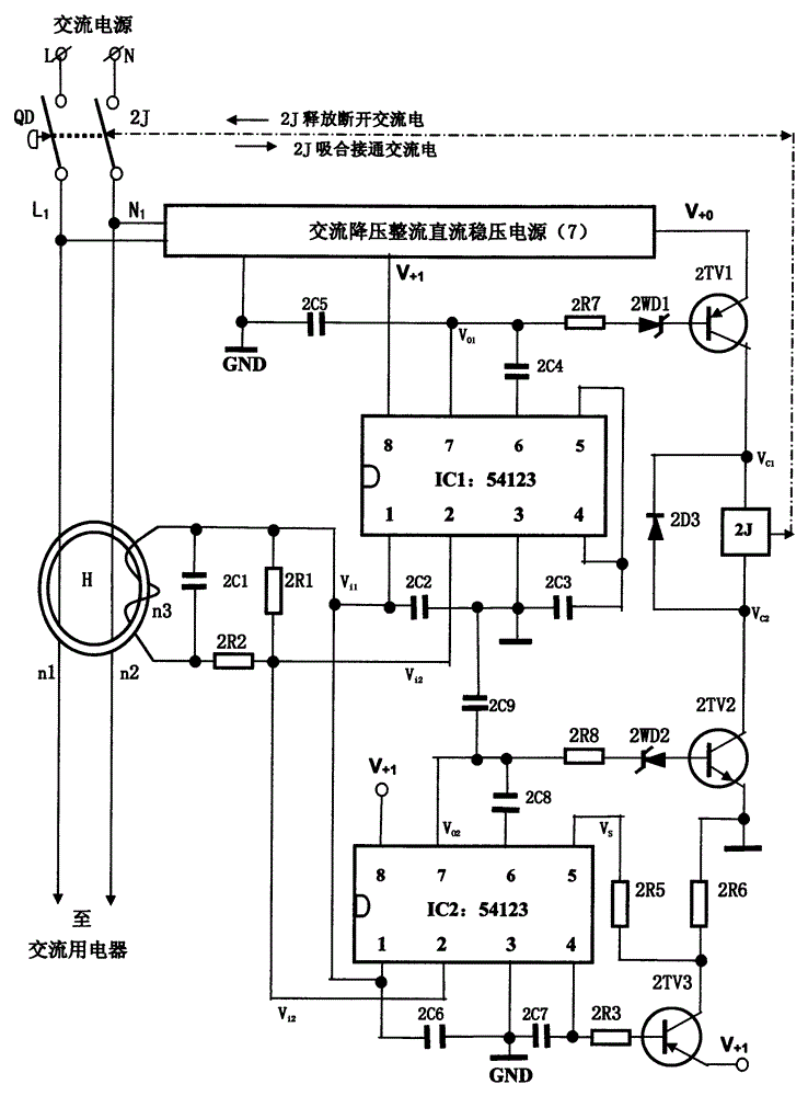
[0027] (one) figure 2 It is the preferred embodiment 1 circuit schematic diagram of the present invention, wherein:

[0028] The zero-sequence current transformer H is composed of an annular iron core, primary coils n1, n2 and secondary coil n3, and the leakage signal adjustment circuit (1) is composed of resistors 2R1, 2R2, and a capacitor 2C1. The first The unit leakage protection control circuit module (2) is composed of leakage protection control circuit IC1 and capacitors 2C2, 2C3, 2C4, 2C5, and the second unit leakage protection control circuit module (3) is composed of leakage protection control circuit IC2 and capacitors 2C6, 2C7, 2C8, 2C9 form, the models of the core IC1 of the leakage protection control circuit module and the core IC2 of the leakage protection control circuit module are all M54123 chips, or chips equivalent to M54123 chip functions, and the guard state setting circuit (4) be made up of triode 2VT3 and resistance 2R3, 2R5, 2R6, described complementa...

Embodiment 2

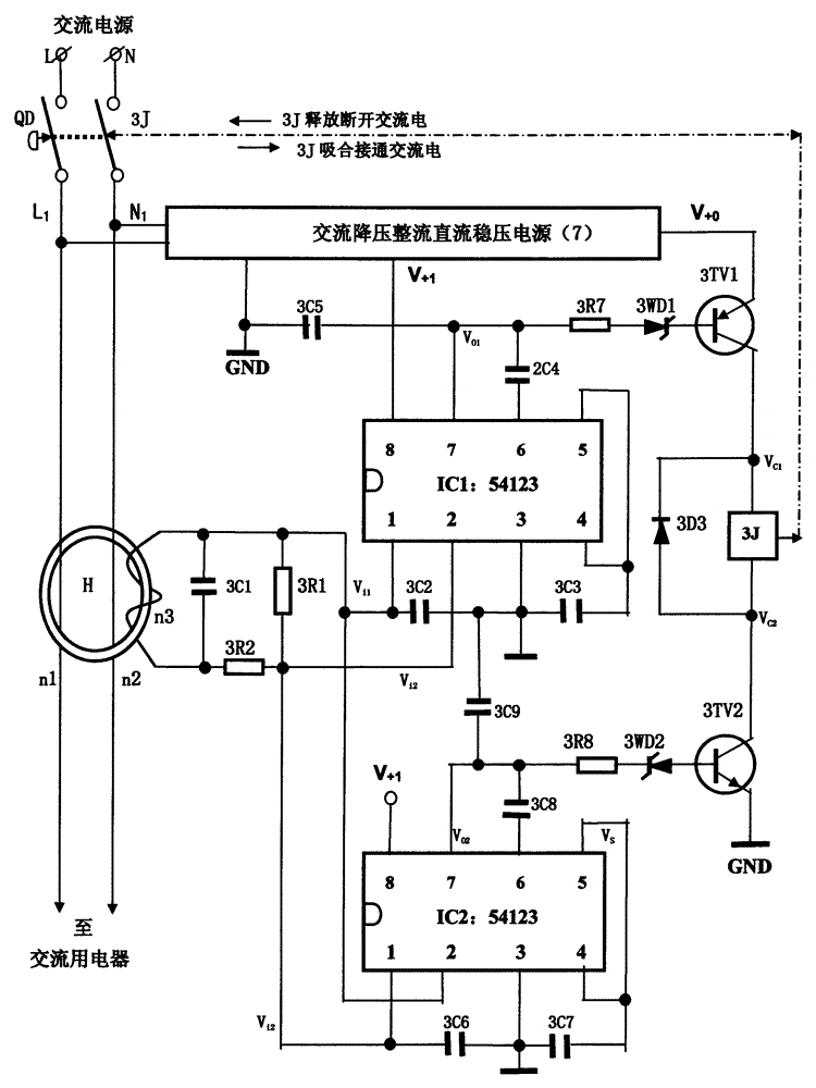
[0038] (one) image 3 It is the preferred embodiment 2 circuit schematic diagram of the present invention, wherein:

[0039] The zero-sequence current transformer H is composed of an annular iron core, primary coils n1, n2 and secondary coil n3, and the leakage signal adjustment circuit (1) is composed of resistors 3R1, 3R2 and capacitor 3C1. The first The unit leakage protection control circuit module (2) is composed of leakage protection control circuit IC1 and capacitors 3C2, 3C3, 3C4, 3C5, and the second unit leakage protection control circuit module (3) is composed of leakage protection control circuit IC2 and capacitors 3C6, 3C7, 3C8, and 3C9 are formed, and the models of the leakage protection control circuit module core IC1 and the leakage protection control circuit module core IC2 are all M54123 chips, or chips equivalent to M54123 chip functions, and the defense state setting circuit (4) The 4th, 5 two pins of the leakage protection control circuit IC2 are directly ...


PUM


Abstract

The invention relates to a very effective leakage protector. The technical scheme adopted by the invention is that the inputs terminals of two or more than two electric leakage protection control circuit module detect and regulate the electric leakage signal in parallel, the output terminal performs series control driving and executes the circuit method to control AC power supply of the AC electric usage device; the electric leakage signal regulation circuit input terminal is connected to the secondary coil of the zero sequence current mutual inductor; the two parallel or more than two electric leakage protection control circuit module is powered by DC voltage V+1; the DC voltage V+0 supplies power to drive and the execution circuit. The beneficial effects of the invention is that the very efficient leakage protector not only can perform safety protection control on the electric leakage or electric shocking of the AC electric device during an normal operation, but also can enforce the driving execution circuit to cut off the AC power supply of the AC electric appliance, so that the AC electric appliance and the electric user are safe and the personal safety can be effectively protected under abnormal condition.

Description

technical field [0001] The present invention relates to an electric shock or electric leakage protector, in particular to an electric leakage protector which can automatically cut off the AC power supply of an AC electrical appliance when an abnormal fault occurs, and can still effectively protect personal safety, referred to as an abnormally effective leakage protector. Background technique [0002] In order to verify the novelty of the present invention, the designer consulted a large number of relevant technical materials (professional books, newspapers and periodicals), and also retrieved relevant patent documents. There are many kinds of existing old leakage protectors, which can basically effectively protect and control the leakage or electric shock of loads or electrical appliances under normal conditions, but there are generally potential fatal defects: when an abnormal fault occurs in itself, its protection function will be reduced. It will fail and form a runaway ...

Claims


Application Information

Patent Timeline
Patent Type & Authority Applications(China)
IPC IPC(8): H02H3/32
Inventor 刘圣平
Owner 刘圣平
Why Eureka
Try Eureka