
The method to prevent the current transformer saturation caused by the DC bias and cause the misoperation of the transformer differential protection

A current transformer and differential protection technology, applied in emergency protection circuit devices, electrical components, etc., can solve problems such as differential protection misoperation, transient saturation, etc., and achieve the effect of ensuring accuracy and reliability

Active Publication Date: 2017-12-19
ELECTRIC POWER SCHEDULING CONTROL CENT OF GUIZHOU POWER GRID CO LTD +2
View PDF6 Cites 0 Cited by
  • Summary
  • Abstract
  • Description
  • Claims
  • Application Information

AI Technical Summary

Problems solved by technology

[0005] In order to solve the technical problem that when the current transformer is affected by the DC bias, after the inrush current of the transformer disappears, the current transformer still works near the saturation point, which will cause its local transient saturation and cause the differential protection to malfunction , the invention discloses a method for preventing differential protection maloperation caused by current transformer saturation caused by DC bias

Method used

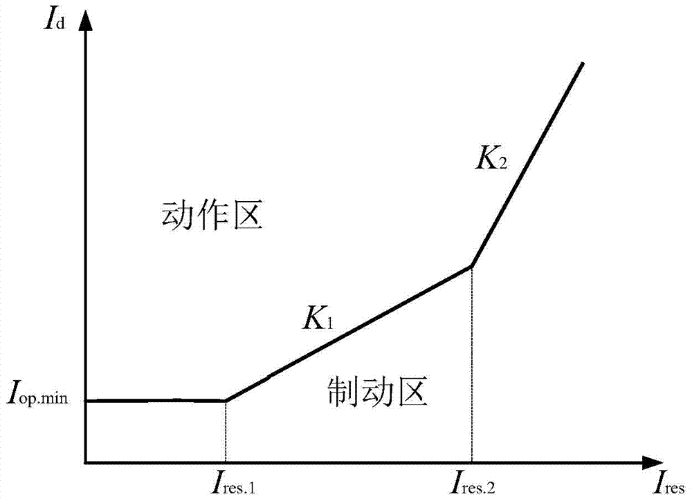
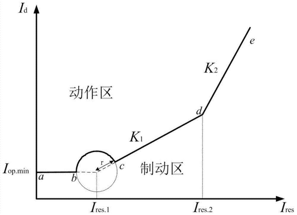
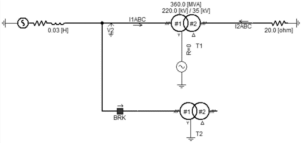

Image

  • The method to prevent the current transformer saturation caused by the DC bias and cause the misoperation of the transformer differential protection
  • The method to prevent the current transformer saturation caused by the DC bias and cause the misoperation of the transformer differential protection
  • The method to prevent the current transformer saturation caused by the DC bias and cause the misoperation of the transformer differential protection

Examples


Embodiment Construction

[0034]The technical solutions of the present invention will be further described in detail below in conjunction with the accompanying drawings and specific embodiments.

[0035] A new method that takes into account the influence of DC bias magnetic field on the current transformer and prevents partial transient saturation of the current transformer when inrush current occurs in the transformer, resulting in misoperation of differential protection.

[0036] Such as Figure 12 Shown is a flowchart of a method for preventing DC bias from causing current transformer saturation to cause maloperation of transformer differential protection. The invention prevents partial transient saturation of current transformers when transformers generate and respond to inrush currents. The following takes the transformer wiring mode as Y / d11 as an example to introduce in detail, and the method includes the following steps:

[0037] (1) Collect the instantaneous current value of the secondary sid...


PUM


Abstract

The invention provides a method for preventing direct current magnetic bias from causing current transformer saturation and transformer differential protection malfunction. The method comprises the steps of judging whether differential protection is started according to phase current jump value start criteria, calculating the second harmonic content of the phase differential current after start, and shutting the differential protection if the second harmonic content is greater than 15%; otherwise judging whether the second harmonic trend criteria is met, determining that a current transformer is in partial transient saturation if the criteria is met and utilizing a corrected ratio brake characteristic curve; otherwise utilizing the conventional ratio brake characteristic curve. The method can identify the partial transient saturation of the current transformer caused by direct current magnetic bias and correct the ratio brake characteristic curve, thereby preventing differential protection malfunction caused by the partial transient saturation of the current transformer and solving the problem that malfunctions tend to occur based on the conventional ratio brake characteristic curve.

Description

technical field [0001] The invention belongs to the technical field of power system relay protection, and particularly relates to a method that takes into account the influence of DC bias magnetism on a current transformer to prevent the current transformer from still working near the saturation point after the inrush current of the transformer disappears, causing its local Transient saturation, a new method of causing misoperation of differential protection. Background technique [0002] In recent years, my country's electric power has developed very rapidly, and the interconnection between power grids in different regions of the country has become increasingly close, making the structure of the entire power system tend to become larger. It is necessary to increase the system transmission capacity and transmission distance to ensure the reliability and quality of electric energy. At this stage, the security and stability of the power grid put forward higher requirements. ...

Claims


Application Information

Patent Timeline
Patent Type & Authority Patents(China)
IPC IPC(8): H02H7/045
Inventor 白加林高昌培王宇恩戴宇赵武智牛静郑涛陆格野赵建新
Owner ELECTRIC POWER SCHEDULING CONTROL CENT OF GUIZHOU POWER GRID CO LTD
Learn More