Implementing method for back photoelectric smoke induction investigator and its device

A technology of photoelectric smoke and its realization method, applied in instruments, alarms, fire alarms, etc., can solve the problems of inability to alarm, insensitivity to black smoke, lens deformation, etc., to maximize the detection area, stable detection sensitivity, intersecting The effect of volume increase

Active Publication Date: 2007-12-19
深圳市赋安安全系统有限公司
View PDF1 Cites 7 Cited by
  • Summary
  • Abstract
  • Description
  • Claims
  • Application Information

AI Technical Summary

Problems solved by technology

[0007] This structure is equipped with lenses at the front end of the transmitting tube and the front end of the receiving tube. Due to the effect of the lens, the transmitting light path and the receiving light path are both cylindrical, and the intersection of the two, that is, the section along the optical central axis of the detection area is a parallelogram. , which greatly limits the size of the detection area, and the smaller detection area makes it difficult to guarantee the azimuth consistency. When a larger detection area is to be obtained, it is necessary to increase the angle between the light emitter and the light receiver or Enlarging the size of the detector itself, increasing the included angle will lead to insensitivity to black smoke, and increasing the size of the detector will bring about a substantial increase in cost; in addition, lenses are installed at the front end of the optical transmitter and optical receiver , it is also prone to lens deformation, high installation difficulty, and high cost. At the same time, dust accumulation on the lens surface or fog accumulation caused by drastic changes in ambient temperature and humidity have a huge impact on the signal. On the one hand, short-term fog accumulation can easily lead to a large signal On the other hand, the accumulation of dust requires regular cleaning, and the installation and cleaning of the lens is extremely difficult, which seriously limits the practicality and long-term use of the detector

Method used


Image

  • Implementing method for back photoelectric smoke induction investigator and its device
  • Implementing method for back photoelectric smoke induction investigator and its device
  • Implementing method for back photoelectric smoke induction investigator and its device

Examples


Embodiment Construction

illustration:

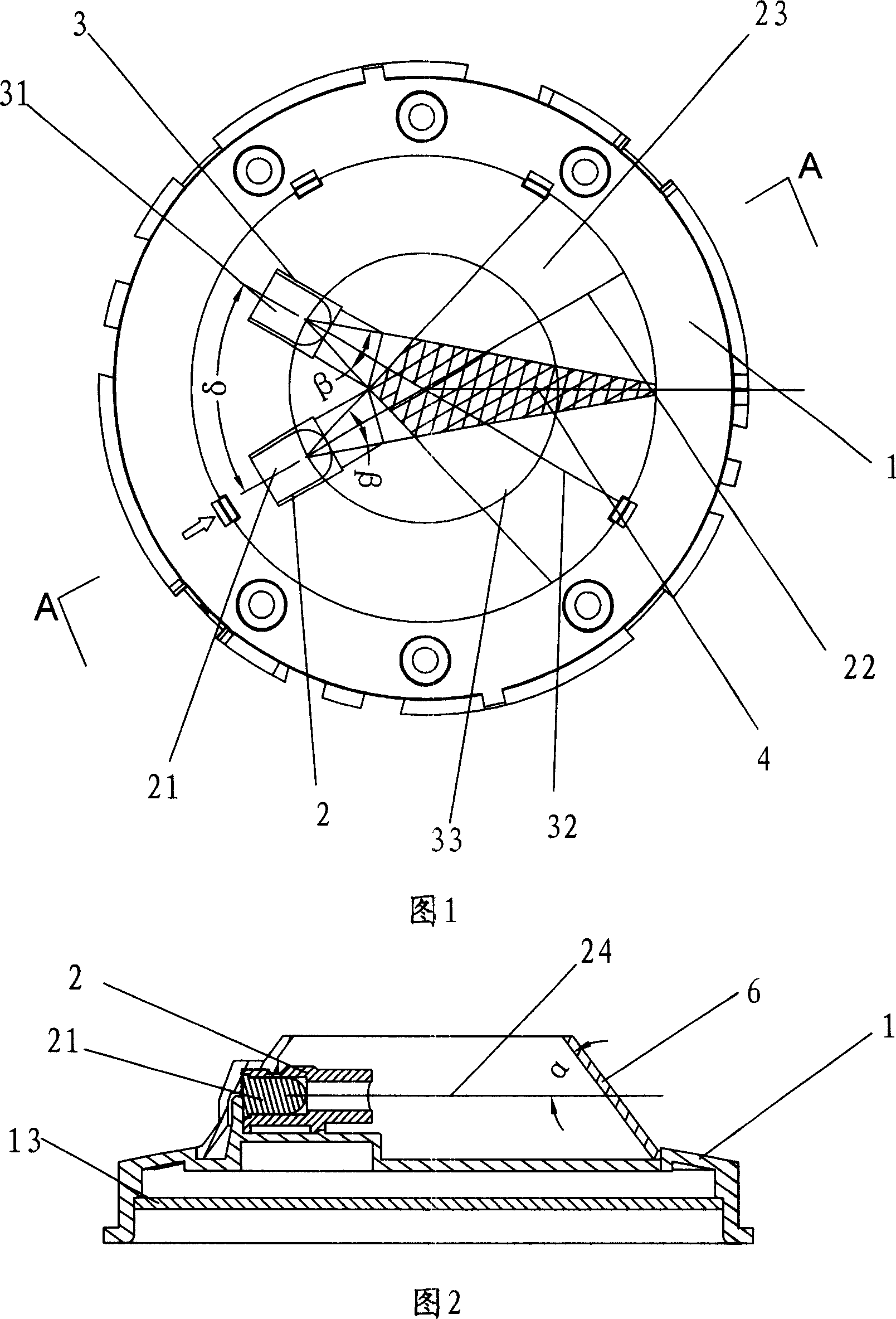
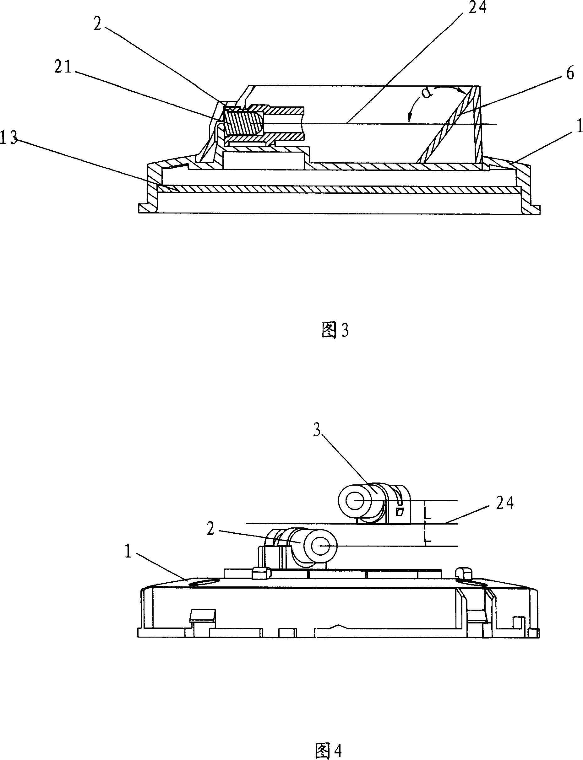
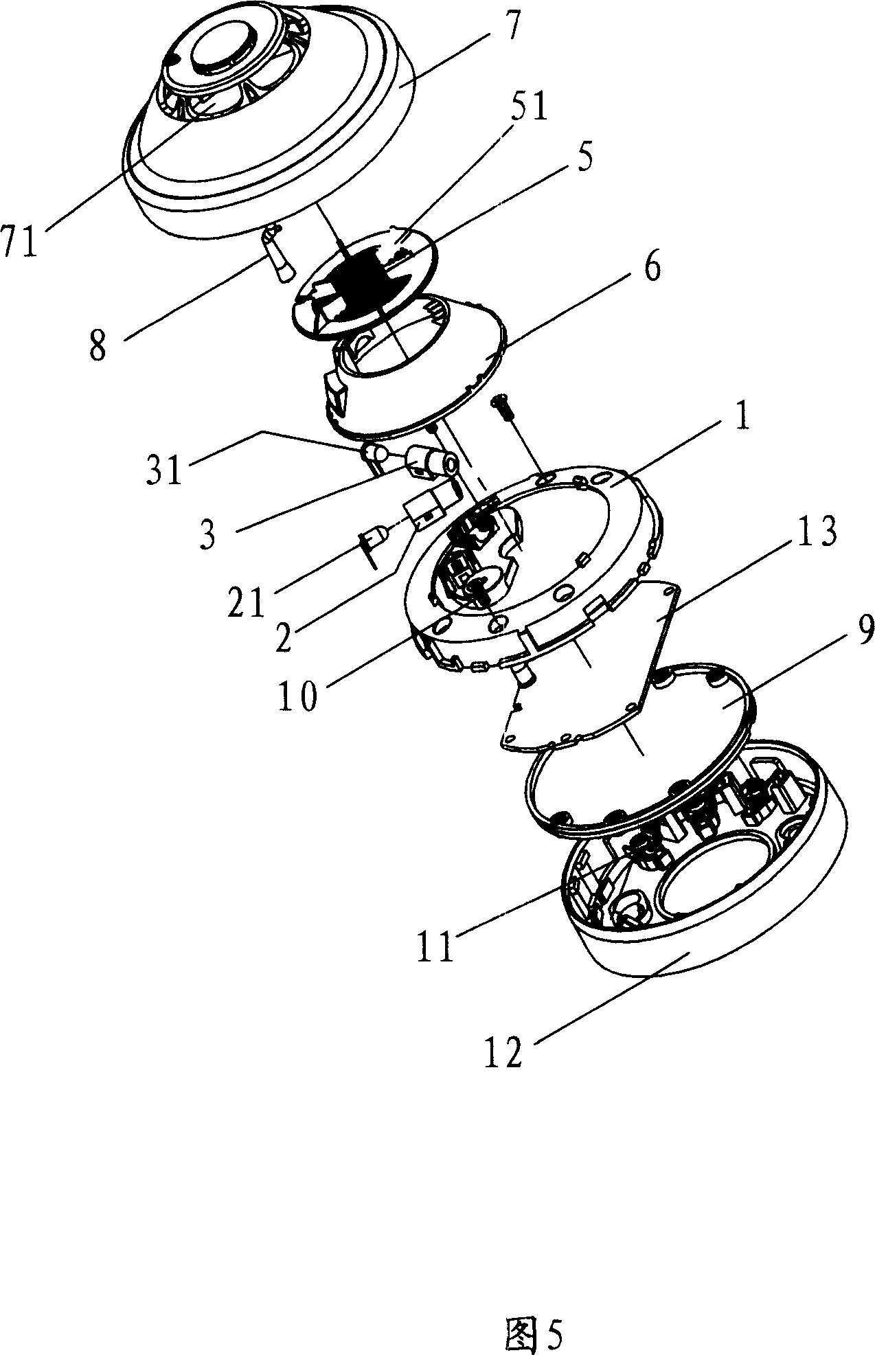
[0034] 1. Base; 2. Transmitting light pipe; 21. Light emitter; 22. Central axis of the light emitted by the light emitter; 23. Transmitting light path; 24. Light plane; 3. Receiving light pipe; 31. Light receiving 32, the optical center axis of the light received by the light receiver; 33 the light receiving path; 4. the detection area; 5. the insect net; 51, the smoke guide bracket; 6. the light shield; 61, the smoke inlet of the light shield; Rib; 63. Inner rib; 64. Slot; 65. Top surface of the hood; 7. Upper cover; 71. Upper cover smoke hole; 8. Light guide post; 9. Back cover; 10. Screw; 11. Wiring terminal; 12. Mounting base; 13. Circuit board.

[0035]The following describes the implementation method of the backward photoelectric smoke detector of the present invention with reference to FIGS. 1 to 3.

[0036] Please refer to Figure 1, Figure 2 and Figure 3, it can be seen from the figure that in the dark room formed by the hood 6 and the base 1, the light emit...


PUM

PropertyMeasurementUnit
angleaaaaaaaaaa

Abstract

A photoelectric smoke detector of backwards type is prepared as arranging detection region formed by crossing emission light path with reception light path in dark chamber formed by base and shading cover, jacketing emission light guide tube and reception light guide tube separately on light emitter and receiver for making emission light path be presented as conical emission path by using light emitter as conical point and reception light path be presented as conical reception path by using light receiver as conical point.

Description

Technical field [0001] The present invention relates to a method for allowing a backward photoelectric smoke detector to have as large a detection area as possible and as little background light as possible, and a photoelectric smoke detector for detecting smoke concentration through the working principle of scattered (reflected) light . Background technique [0002] Photoelectric smoke detectors use the principle of infrared light to scatter (reflection) in smoke particles to achieve smoke detection. It is generally composed of darkrooms, light emitters, light receivers, and related structures and circuits. [0003] The existing photoelectric smoke detectors can be divided into forward photoelectric smoke detectors and backward photoelectric smoke detectors from the perspective of the arrangement of the light transmitter and light receiver. The so-called backward photoelectric smoke detectors refer to The angle between the optical center axis of the light emitted by the light em...

Claims


Application Information

Patent Timeline
Patent Type & Authority Applications(China)
IPC IPC(8): G01N21/49G08B17/107
Inventor 吴明发颜泽玉
Owner 深圳市赋安安全系统有限公司
Why Eureka
Try Eureka