Vehicle eddy current brake

An eddy current brake and vehicle technology, applied in the direction of asynchronous inductive clutch/brake, etc., can solve the problems of high purchase cost, poor maintainability, low reliability, etc. Extensive effect

Active Publication Date: 2015-10-21
ACADEMY OF ARMORED FORCES ENG PLA +1
View PDF9 Cites 0 Cited by
  • Summary
  • Abstract
  • Description
  • Claims
  • Application Information

AI Technical Summary

Problems solved by technology

[0005] The patent with the application number CN201120108573 discloses a disc type electric eddy current brake, but the design of this eddy current brake is too complicated and the environmental adaptability is poor. In harsh environments such as low and high temperatures, the reliability is poor, the maintainability is poor, the maintenance is complicated, the requirements for guarantee, maintenance personnel are relatively high, and the experience level is relatively high, and the purchase cost is high, and the maintenance cost is also high. It is only suitable for installation on rotating machinery. on the shaft, but not suitable for installation on the wheels of tracked vehicles; similarly, the patent application number CN96117543 discloses a kind of automatic fast safety braking device for automobiles, the design of this kind of eddy current brake is a little complicated, and the environmental adaptability Strong, the reliability is not high in dusty, low and high temperature and other harsh environments, it is only suitable for installation on the shaft of rotating machinery, not suitable for installation on the wheels of tracked vehicles, and the heat dissipation is poor, it is very easy to install in high temperature environments damage; similarly, a disc-type eddy current buffer with the application number CN200820188409 also has the disadvantages of complex design, poor environmental adaptability, poor heat dissipation, and easy damage in high-temperature environments

Method used


Image

  • Vehicle eddy current brake
  • Vehicle eddy current brake
  • Vehicle eddy current brake

Examples


Embodiment Construction

[0023] The following will clearly and completely describe the technical solutions in the embodiments of the present invention with reference to the accompanying drawings in the embodiments of the present invention. Obviously, the described embodiments are only some, not all, embodiments of the present invention. All other embodiments obtained by persons of ordinary skill in the art based on the embodiments of the present invention belong to the protection scope of the present invention.

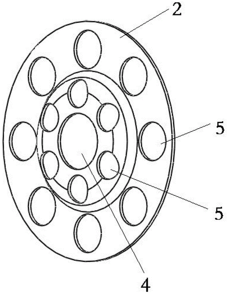
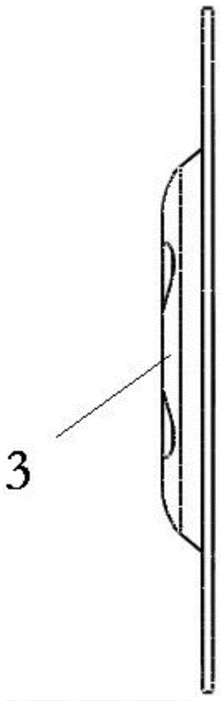
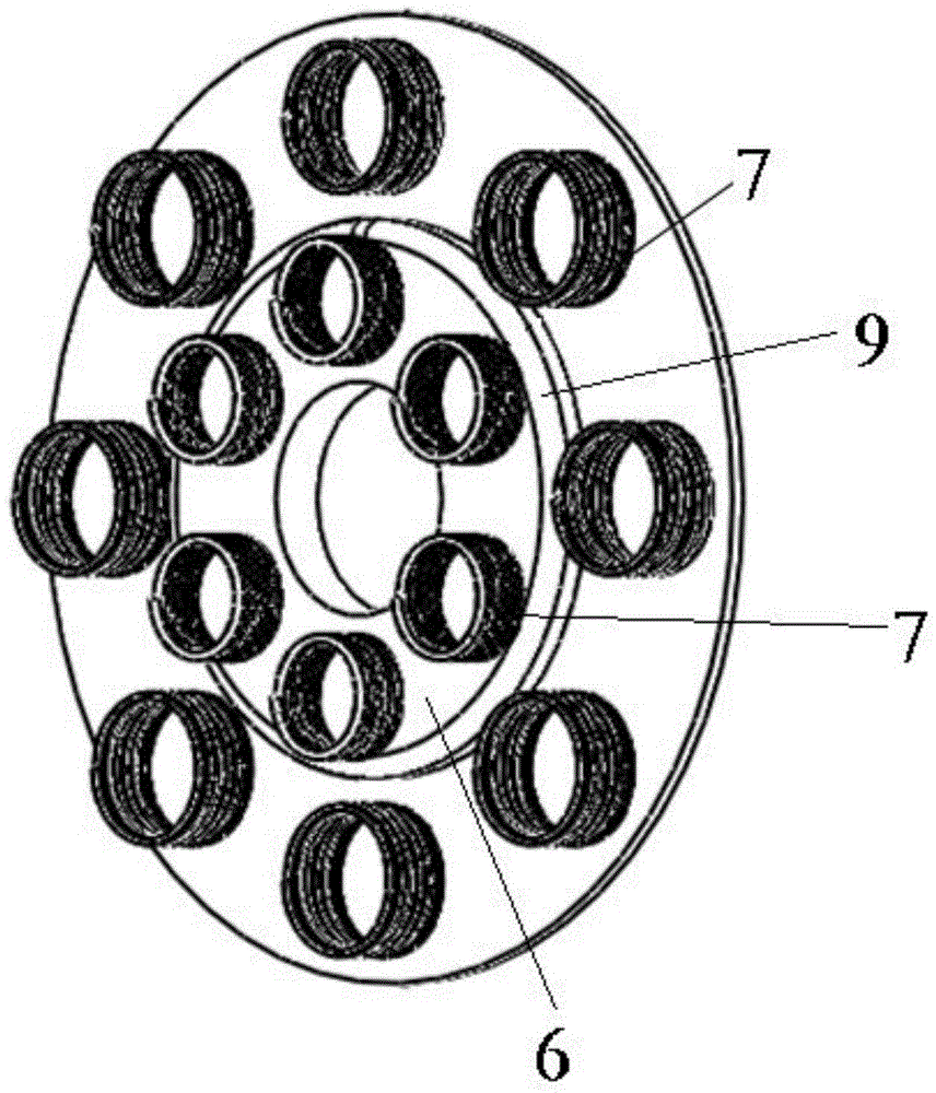
[0024] Such as Figure 1-5 As shown, a vehicle eddy current brake according to an embodiment of the present invention includes a stator disc 1 and a spacer 2 cooperating with the stator disc 1; the center of the spacer 2 is provided with a coaxially fitted depression part 3, the center of the recessed part 3 is provided with a coaxial through hole 4, and the spacer 2 and the recessed part 3 are respectively evenly distributed with a number of round holes 5 with the center as the center of the...


PUM


Abstract

The invention discloses a vehicle eddy current brake, comprising a stator disc and a separation plate in cooperation with the stator disc; the center of the separation plate is provided with a coaxially cooperative concave part; the center of the concave part is provided with a coaxially cooperative through hole; the separation plate and the concave part are both uniformly provided with a plurality of holes with respective centers as circle centers; the stator disc is provided with a projection part in cooperation with the concave part; the stator disc and the projection part are both uniformly provided with a plurality of coil magnetic cores in cooperation with the holes and with respective centers as circle centers, wherein the periphery of the projection part is provided with circular beads. In addition, the vehicle eddy current brake also comprises a cooperative additional disc. The vehicle eddy current brake can speed down and brake rapidly, substantially improve the safety in vehicle high speed brake, meanwhile overcome the disadvantages of proneness to heating and great calorific values, and have the advantages of simple structure, easy maintenance, and high maintainability, reliability and scalability.

Description

technical field [0001] The invention relates to an eddy current brake, in particular to a vehicle eddy current brake. Background technique [0002] Eddy current, also known as eddy current, refers to the current formed inside a conductor under electromagnetic induction. Eddy current brakes are usually used in conjunction with traditional brakes to control the speed of most commercial vehicles (large and medium-sized passenger cars and trucks), so they are often called eddy current retarders. [0003] Ordinary vehicles mostly rely on the mechanical friction between friction materials to stop them from moving, but they are driven by different driving methods such as mechanical linkages, hydraulic oil or compressed air, while electric eddy current braking technology does not require There is actual friction, but the braking force is generated electromagnetically to achieve the braking effect. [0004] The eddy current retarder decelerates by the force of the eddy current. Wh...

Claims


Application Information

Patent Timeline
Patent Type & Authority Applications(China)
IPC IPC(8): H02K49/04
Inventor 张豫南张舒阳房远宁克炎颜南明张芳尚颖辉李年裕张健方青峰黄涛杨怀斌张杰王志辉
Owner ACADEMY OF ARMORED FORCES ENG PLA
Why Eureka
Try Eureka