Application method and application facility

A coating and primer technology, applied in the direction of coating, device for coating liquid on the surface, spray device, etc., to achieve the effect of high application efficiency and increased quantity

Active Publication Date: 2015-10-21
DUERR SYST GMBH
View PDF11 Cites 15 Cited by
  • Summary
  • Abstract
  • Description
  • Claims
  • Application Information

AI Technical Summary

Problems solved by technology

[0003] However, this known application method by means of a jet of droplets is not entirely satisfactory

Method used


Image

  • Application method and application facility
  • Application method and application facility
  • Application method and application facility

Examples


Embodiment Construction

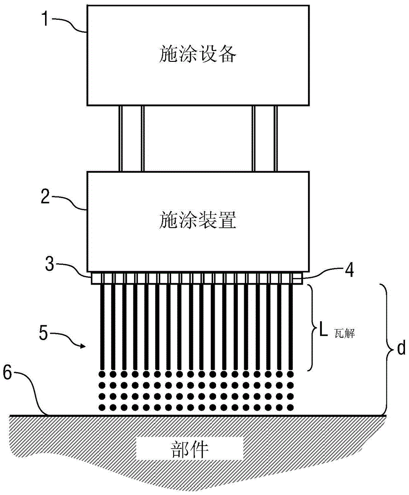
[0049] Figure 1 shows a conventional application system known for example from DE 10 2010 019 612 A1. Here, the application device 1 supplies the application device 2 with the required medium, for example the coating medium to be applied, which may be paint, for example.

[0050] The application device 2 has a perforated plate 3 in which a plurality of application nozzles 4 are formed. Each application nozzle 4 of the perforated plate 3 emits a coating medium jet 5, wherein, just after being emitted from the application nozzle 4, the coating medium jet 5 is initially along the jet direction at a disintegration distance L collapse The internal cohesion and then collapse into droplets, the reason why droplet collapse is enforced specifically in this traditional application system is vibration access.

[0051] The application device 2 is positioned at an application distance d relative to the component 6 to be coated, wherein the positioning is achieved in such a way that the applica...


PUM


Abstract

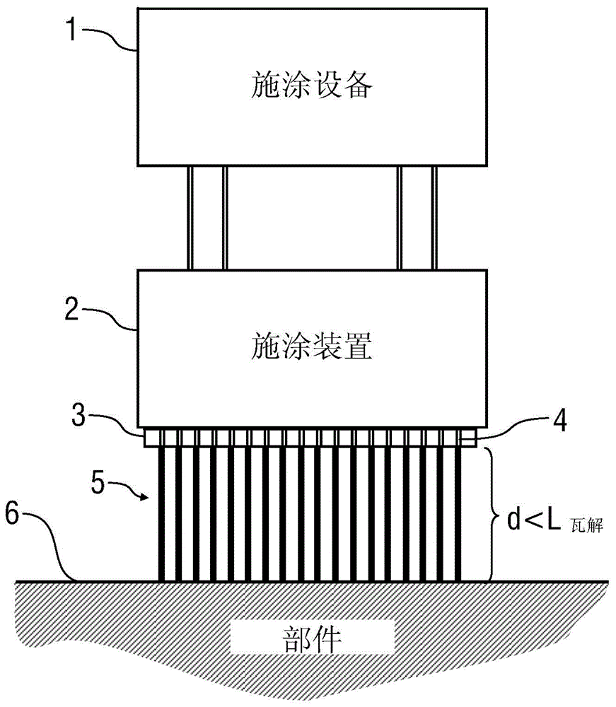
The invention relates to an application method for applying a coating agent, in particular a varnish or paint, a sealant, a separating agent or an adhesive, to a component (6), in particular to a motor vehicle body component. The application method comprises the following steps: dispensing a coating agent jet (5) from an application device (2) and positioning the application device (2) relative to the component (6) at a defined application distance (d) between the application device (2) and the component (6) such that the coating agent jet (5) strikes the component (6) and coats the component (6). According to the invention, the application distance (d) is less than the collapse length (LZERFALL) of the coating agent jet (5) so that the coating agent jet (5) strikes the component (6) with its continuous portion. The invention further relates to a corresponding application facility.

Description

Technical field [0001] The present invention relates to an application method and application system for applying a coating medium (such as paint, sealant, mold release agent, adhesive, functional layer) to a component (such as a motor vehicle body part). Background technique [0002] The patent publication DE 10 2010 019 612 A1 discloses a coating method in which a jet of droplets of a coating medium is generated, which impinges on the surface of the part to be coated. The disintegration of the droplets of the initial continuous spray of coating material is specifically forced to occur by vibration input, so that the disintegration distance of the spray of coating material is smaller than the spraying distance, that is, the distance between the application device and the surface of the component. [0003] However, this known application method by means of a jet of droplets is not entirely satisfactory. [0004] Reference is also made to the prior art regarding DE 38 35 078 C2 and D...

Claims


Application Information

Patent Timeline
IPC IPC(8): B05D5/06B05C5/02B05D1/02
CPCB05D1/02B05B12/124B05C5/027B05C11/1018B05D5/06B05D2252/00B05B1/14B05B1/02
Inventor H-G·弗里茨B·沃尔M·克莱纳T·贝尔F·赫勒
Owner DUERR SYST GMBH
Why Eureka
Try Eureka