Cornea ablation method for customized vision correction

A cutting method, vision correction technology, used in ophthalmic surgery and other directions

Inactive Publication Date: 2015-10-28
SICHUAN UNIV
View PDF1 Cites 6 Cited by
  • Summary
  • Abstract
  • Description
  • Claims
  • Application Information

AI Technical Summary

Problems solved by technology

The defect of this method is that it is a corneal ablation scheme designed based on the wavefront aberration data of the whole eye. Although this scheme considers the oblique incidence of the front surface of the cornea, it is based on the assumption that the cornea is a standard spherical surface or a standard ellipsoidal surface

Method used


Image

  • Cornea ablation method for customized vision correction
  • Cornea ablation method for customized vision correction
  • Cornea ablation method for customized vision correction

Examples


Embodiment Construction

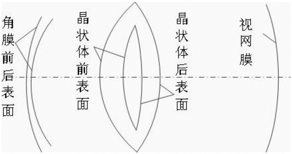
[0020] The model eye that the present invention adopts is the precision model eye of Gullstrand six refraction surface, as

[0021] figure 1 shown. The structural parameters of the Gullstrand model eye are shown in Table 1.

[0022] Table 1 Structural parameters of Gullstrand precision model eye with six refraction surfaces

[0023]

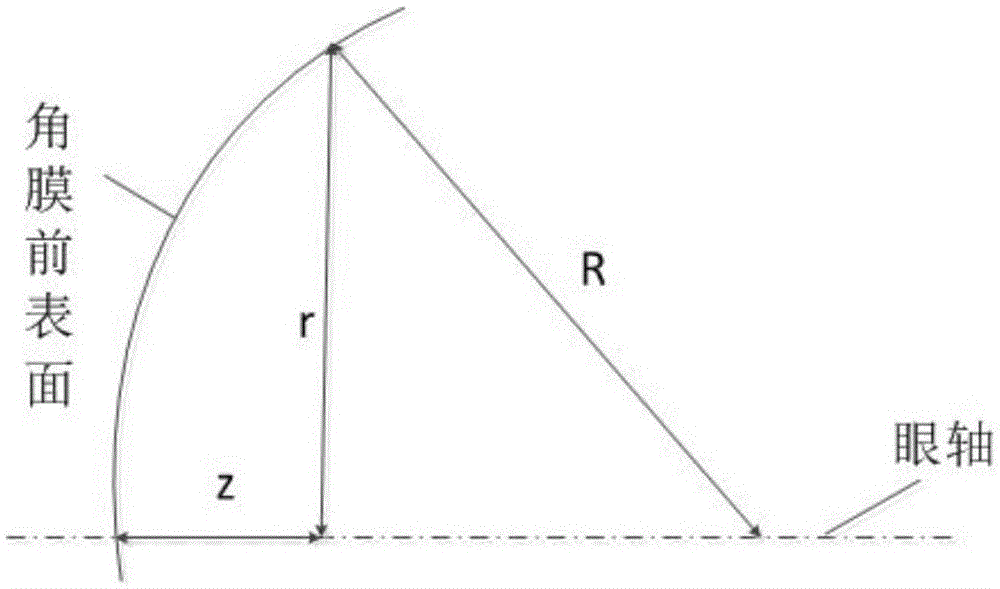
[0024] This patent takes -7.5D individual myopia as an example. The measurement data of the corneal topography of the human eye is provided by Yibin Second People's Hospital, and the data of the corneal topography is the corresponding diopter size at a certain aperture height, as shown in Table 2 Shown in columns 1-2. Convert the diopter size into the radius of curvature under each polar coordinate radius of the cornea, and use an even-order aspheric surface to fit the anterior corneal surface of individual myopic eyes.

[0025] The expression for the sagittal height of an even-order aspheric surface:

[0026] z = ...


PUM


Abstract

The invention discloses a cornea ablation method for customized vision correction. According to the invention, the shape of the front surface of a cornea is constructed through a backlight tracing manner, and the data of the cornea front surface before and after the design can be converted into the depth for the customized cornea ablation. By employing the method, the cornea ablation contour in eye refractive surgery can be more accurate, and better surgical correction effects can be achieved.

Description

technical field [0001] The invention relates to a corneal cutting method for personalized vision correction, in particular to a corneal cutting method for designing personalized human vision correction by adopting a reverse ray tracing method. Background technique [0002] In daily life, most of people's information is obtained through the eyes. Because the information obtained through vision is of great significance to our life, the research on vision is particularly important. In contemporary society, many people have abnormal vision due to many different reasons, which brings a lot of inconvenience to their lives. Among them, the most common vision problem is nearsightedness. There are also many factors that lead to the formation of myopia. The more common reasons are: 1. Due to the excessive curvature of the cornea of ​​the eye (that is, the radius of curvature of the front surface of the cornea is smaller than that of a normal human eye), the focal position of the imag...

Claims


Application Information

Patent Timeline
Patent Type & Authority Applications(China)
IPC IPC(8): A61F9/013
Inventor 李大海陈志洁章辰章涛王琼华
Owner SICHUAN UNIV
Why Eureka
Try Eureka