Movable type purifying machine

A purification machine and mobile technology, applied in chemical instruments and methods, electrostatic effect separation, dispersed particle filtration, etc., can solve the problems of large breathing resistance, small power per unit volume, heavy weight, etc.

Inactive Publication Date: 2015-10-28
张跃
View PDF4 Cites 4 Cited by
  • Summary
  • Abstract
  • Description
  • Claims
  • Application Information

AI Technical Summary

Problems solved by technology

[0002] Existing mobile purifiers have disadvantages such as large volume, heavy weight, inconvenient portabili...

Method used


Image

  • Movable type purifying machine
  • Movable type purifying machine
  • Movable type purifying machine

Examples


Embodiment Construction

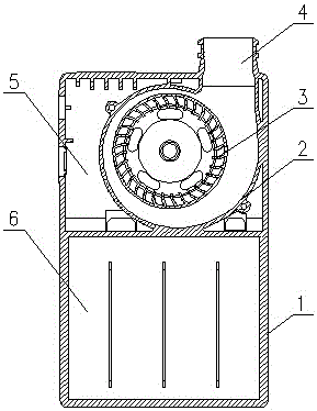
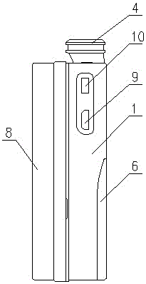
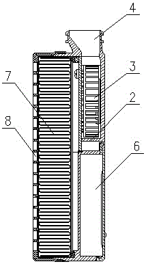
[0018] like Figure 1-3 As shown, a mobile purifier includes a bottom shell 1, a filter cover 8, a filter 7, and a centrifugal fan 3.

[0019] The lower half of the bottom case 1 is provided with a storage battery 6 , and the upper part of the bottom case 1 is provided with a centrifugal fan 3 with a volute air duct 2 which is connected with the bottom case 1 as a whole. The spiral air duct 2 itself is designed as an integral part of the bottom case 1, which not only greatly reduces the thickness and volume of the bottom case 1, but also improves the filtration efficiency and purification effect of the centrifugal fan 3.

[0020] The outlet of the volute air channel 2 is connected with the ventilation interface 4 on the bottom shell 1, and the ventilation interface 4 is connected with the ventilation terminal through a conduit, and the ventilation terminal is a mask, or a face mask, or a nasal cavity inserter. Several annular retaining rings are arranged on the outside of the...


PUM


Abstract

The invention relates to a movable type purifying machine, which comprises a storage battery, a bottom case, a filter and a centrifugal fan. The centrifugal fan is installed in the bottom case with a volute air duct. The volute air duct and the bottom case are connected as a whole. The circumference of the centrifugal fan is provided with a circuit board with a central hole. The size of the central hole is matched with the size of the centrifugal fan. A gap between the circumference of the circuit board and the bottom case is sealed by a sealing strip. The movable type purifying machine is small in size, light in weight, easy to carry, large in air-supply power and filtering power, and good in comfortableness.

Description

technical field [0001] The invention relates to an air filtering and purifying device, in particular to a portable portable purifier. Background technique [0002] Existing mobile purifiers have the disadvantages of large volume, heavy weight, inconvenient portability, high breathing resistance, poor comfort, low power per unit volume, poor filtering and purification effects, and the like. Contents of the invention [0003] The purpose of the present invention is to overcome the deficiencies of the existing technology and provide a new type of thin purifier with small volume, light weight, easy to carry, high air supply and filtering power, small breathing resistance and good comfort. [0004] The present invention is achieved through the following technical solutions: [0005] The mobile purifier includes a battery, a bottom shell, a filter, and a centrifugal fan. The battery and the filter are installed in the bottom shell. The centrifugal fan is installed in the bo...

Claims


Application Information

Patent Timeline
IPC IPC(8): B01D46/00B03C3/00
Inventor 张跃
Owner 张跃
Why Eureka
Try Eureka