Warp beam loading and unloading machine

A loading and unloading machine and warp beam technology, which is applied in the direction of liquid/gas/steam processing of a certain length of textile materials, metal processing equipment, and processing of textile material carriers, etc., which can solve problems such as danger, low production efficiency, and large operating physical exertion

Active Publication Date: 2015-10-28
TAIAN COMPANION MACHINERY
View PDF8 Cites 8 Cited by
  • Summary
  • Abstract
  • Description
  • Claims
  • Application Information

AI Technical Summary

Problems solved by technology

The height of workers is required to be more than 1.7 meters, the operation consumes a

Method used


Image

  • Warp beam loading and unloading machine
  • Warp beam loading and unloading machine
  • Warp beam loading and unloading machine

Examples


Embodiment Construction

[0026] The preferred embodiments of the present invention will be described in detail below in conjunction with the accompanying drawings, so that the advantages and features of the present invention can be more easily understood by those skilled in the art, so as to define the protection scope of the present invention more clearly.

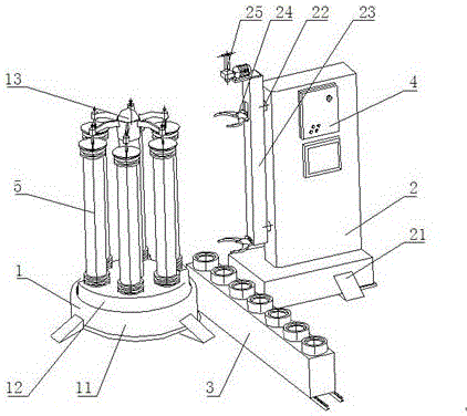
[0027] refer to figure 1 As shown, a warp beam loading and unloading machine provided by the present invention includes a rotating base 1, a manipulator part 2 opposite to the rotating base 1, and a warp beam transport vehicle 3 is also arranged between the rotating base 1 and the manipulator part 2;

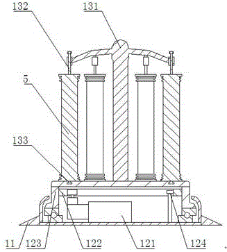
[0028] Rotary base 1 comprises a base 11, is provided with a rotating mechanism 12 on the base, and a dyeing sarong 13 that can clamp a plurality of warp beams 5 is installed on the rotating mechanism 12;

[0029] Manipulator part 2 comprises a support 21, and support 21 is connected with lift mechanism 23 by a telescoping mechanism 22, and lift me...


PUM


Abstract

The invention discloses a warp beam loading and unloading machine which comprises a rotating base, a mechanical hand component and a warp beam transport vehicle. The rotating base comprises a rotating mechanism. The rotating mechanism is provided with a dyeing yarn cage capable of clamping a plurality of warp beams. An existing yarn cage or dyeing cage can be adopted as the dyeing yarn cage. The mechanical hand component comprises a telescoping mechanism and a lifting mechanism which are connected with each other. The lifting mechanism is connected with a mechanical hand used for clamping the warp beams and a locking mechanism used for locking the warp beams. The mechanical hand corresponds to the dyeing yarn cage in position. The warp beam loading and unloading machine further comprises a control device used for controlling the warp beam loading and unloading machine to act. The warp beams are clamped by the dyeing yarn cage in the rotating base; the rotating mechanism can rotate the warp beams to the position where the mechanical hand can grab the warp beams; the mechanical hand is controlled by the telescoping mechanism and the lifting mechanism to move and grab the warp beams; the transmission mechanisms are controlled by the control device to run in order.

Description

technical field [0001] The invention relates to the technical field of textiles, in particular to a warp beam loading and unloading machine. Background technique [0002] The traditional operation is to manually cooperate with the crane to lift the warp beam into or out of the dyeing cage, and manually lock and fix or loosen the warp beam. The height of the workers is required to be more than 1.7 meters, the operation consumes a lot of energy, the production efficiency is low, and there is a certain degree of danger. Contents of the invention [0003] The invention mainly solves the technical problems existing in the prior art, thereby providing a warp beam loading and unloading machine which is convenient to replace warp beams, has high degree of automation and high production efficiency. [0004] Above-mentioned technical problem of the present invention is mainly solved by following technical scheme: [0005] The warp beam loading and unloading machine of the present ...

Claims


Application Information

Patent Timeline
IPC IPC(8): B23P19/00
CPCB23P19/00D06B5/18D06B23/04
Inventor 陈队范
Owner TAIAN COMPANION MACHINERY
Why Eureka
Try Eureka