
Positioning sleeve part for spindle brake device of braider

A technology of a braking device and a positioning sleeve, which is applied in the field of knitting machines, can solve the problems of unable to brake the bobbin, the pressure spring is easy to break, and the elastic range is small, and the effect of the spindle braking is sensitive and the adjustment is convenient.

Active Publication Date: 2015-10-28
浙江本发科技有限公司
View PDF8 Cites 6 Cited by
  • Summary
  • Abstract
  • Description
  • Claims
  • Application Information

AI Technical Summary

Problems solved by technology

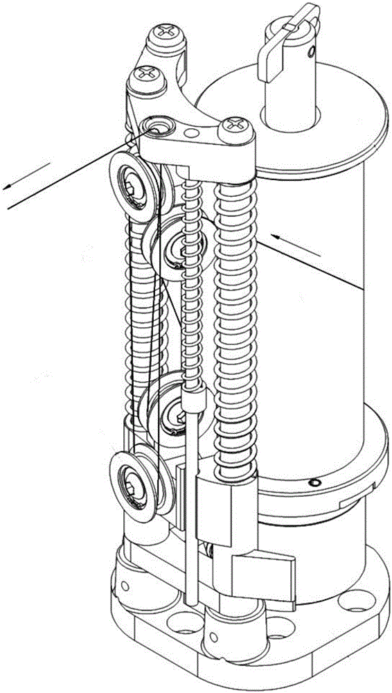
For this reason, we applied the research and development results to 201310136782 "Tension Control of Braiding Machine Spindle and Torsion Spring Steel Coil Braking Device". After more than two years of sales of patented products, it is very popular with customers, but old customers who care about us also gave feedback Some improvement suggestions: For example, the spindle has been used for a long time, and the torsion spring is worn out, and the spool cannot be stopped.
Moreover, when adjusting, it is necessary to remove the torsion spring positioning sleeve and the support rod seat, and the direction of the support rod needs to be adjusted to adjust the holding force of the torsion spring; the compression spring used for reset is easy to break, the elastic range is too small, etc.

Method used


Image

  • Positioning sleeve part for spindle brake device of braider
  • Positioning sleeve part for spindle brake device of braider
  • Positioning sleeve part for spindle brake device of braider

Examples


Embodiment 1

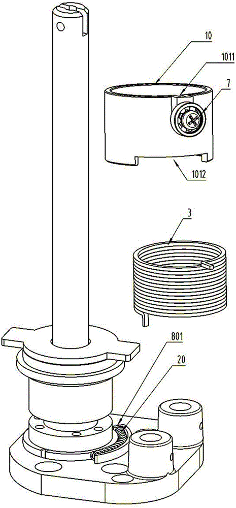
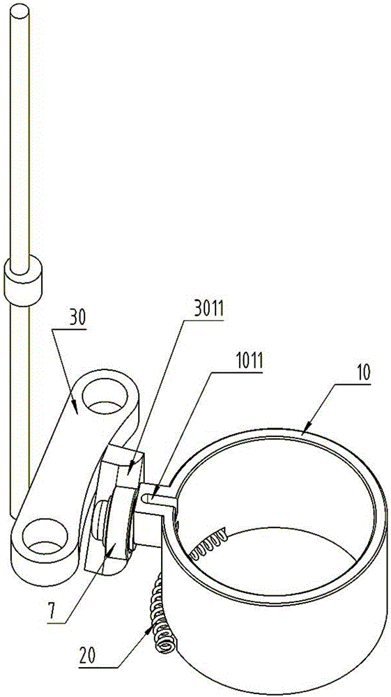
[0027] The structure of the positioning sleeve parts of the braiding machine spindle brake device is as follows: Figure 5 - Figure 9 As shown, it includes: positioning sleeve 1, adjustment seat 2, steel wire torsion spring seat 4, steel wire torsion spring 5, push-pull piece 6, roller 7;

[0028] see Figure 8 and Figure 9 , the positioning sleeve 1 is a cylinder, and a steel coil torsion spring 3 is installed in the middle through hole; the middle through hole and the outer wall of the positioning sleeve cylinder are not arranged on the same axis line, and a convex positioning collar is arranged at the lower end of the positioning sleeve 15. The convex ring 15 of the positioning sleeve and the through hole in the middle of the positioning sleeve 1 are set on the same axis, and the convex ring of the positioning sleeve rests on the pit at the upper end of the adjustment seat 2; the upper end of the positioning sleeve 2 is provided with a bayonet 11 for Accommodate the st...


PUM


Abstract

The invention discloses a positioning sleeve part for a spindle brake device of a braider. The positioning sleeve part comprises a positioning sleeve, a regulation seat, a steel wire torsion spring, a push-pull piece and a roller, wherein a through hole in the middle part of the positioning sleeve and an outer wall of the positioning sleeve are not positioned on the same axis; a positioning sleeve convex ring is arranged at the lower end of the positioning sleeve; the positioning sleeve convex ring and the through hole in the middle part of the positioning sleeve are positioned on the same axis; the positioning sleeve convex ring is arranged on a pit in the upper end of the regulation seat; a bayonet is formed in the upper end face of the positioning sleeve, and is used for accommodating a steel coil torsion spring cross arm; the roller is fixedly arranged on the outer wall of the positioning sleeve; the regulation seat is a circular ring, and a bayonet is formed in the inner wall of the regulation seat, and is used for accommodating a steel coil torsion spring vertical arm; the regulation seat is fixedly arranged on a convex column of a rack through a screw; through holes are formed in the walls of steel wire torsion spring seats, and are used for accommodating an upper arm or a lower arm of the steel wire torsion spring to fix the steel wire torsion spring seat on the rack; through holes are formed in the two ends of the push-pull piece; one end of the push-pull piece is fixedly arranged on the steel wire torsion spring, and the other end of the push-pull piece is fixedly arranged on the positioning sleeve. The positioning sleeve part has the advantage that the spindle brake is more sensitive, and is more convenient to regulate.

Description

technical field [0001] The invention relates to the technical field of knitting machines, in particular to a positioning sleeve part of a brake device for a spindle of a knitting machine. Background technique [0002] High-pressure oil hoses, gas hoses, cable hoses, etc., and even water hoses for bathrooms, all need to be braided with a protective layer on the outer layer, and braided wires such as metal wires or nylon wires are wound into a net. The general structure of our country's knitting machine is that there are more than 20 spindles walking on the panel around the central hose in an S-shaped trajectory, and the braiding wire is wound on the central hose during the process. The weaving process requires the spindles to flow continuously , Supply the braiding yarn with constant tension. If the yarn of one of the spindles is used up or broken, the whole machine will automatically shut down. . When the power is suddenly cut off, all the spindles with silk will continue ...

Claims


Application Information

Patent Timeline
IPC IPC(8): D04C3/40
CPCD04C3/40
Inventor 梁贤军梁宽薛林晓
Owner 浙江本发科技有限公司
Learn More