
Anhydrous humidification equipment and air conditioning systems

A humidification equipment and humidity storage technology, applied in air conditioning systems, lighting and heating equipment, heating methods, etc., can solve the problems of insufficient water, inconvenient use, and inconspicuous humidification without water. The effect of dense and simple structure

Active Publication Date: 2017-07-18
MIDEA GRP CO LTD
View PDF7 Cites 0 Cited by
  • Summary
  • Abstract
  • Description
  • Claims
  • Application Information

AI Technical Summary

Problems solved by technology

[0002] For a long time, in order to improve the comfort of the air conditioner, competitors in the production of air conditioners have added the function of anhydrous humidification when the air conditioner is cooling or heating, but after market research, the humidity storage and humidification effect of anhydrous humidification cannot be achieved The expected effect generally shows that the amount of water produced during the process of storage and humidification of anhydrous humidification is insufficient, resulting in an inconspicuous amount of anhydrous humidification. In addition, in order to continuously realize the anhydrous humidification function of the air conditioner, it is often necessary to manually replace the storage. Wet block or adjust the position of the moisture storage block, resulting in extremely inconvenient use

Method used


Image

  • Anhydrous humidification equipment and air conditioning systems
  • Anhydrous humidification equipment and air conditioning systems
  • Anhydrous humidification equipment and air conditioning systems

Examples


Embodiment Construction

[0038] The technical solutions of the present invention will be further described below in conjunction with the accompanying drawings and specific embodiments. It should be understood that the specific embodiments described here are only used to explain the present invention, not to limit the present invention.

[0039] The invention proposes a waterless humidifying device.

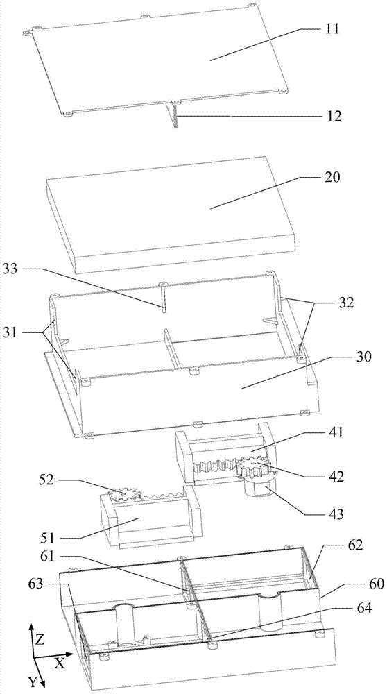
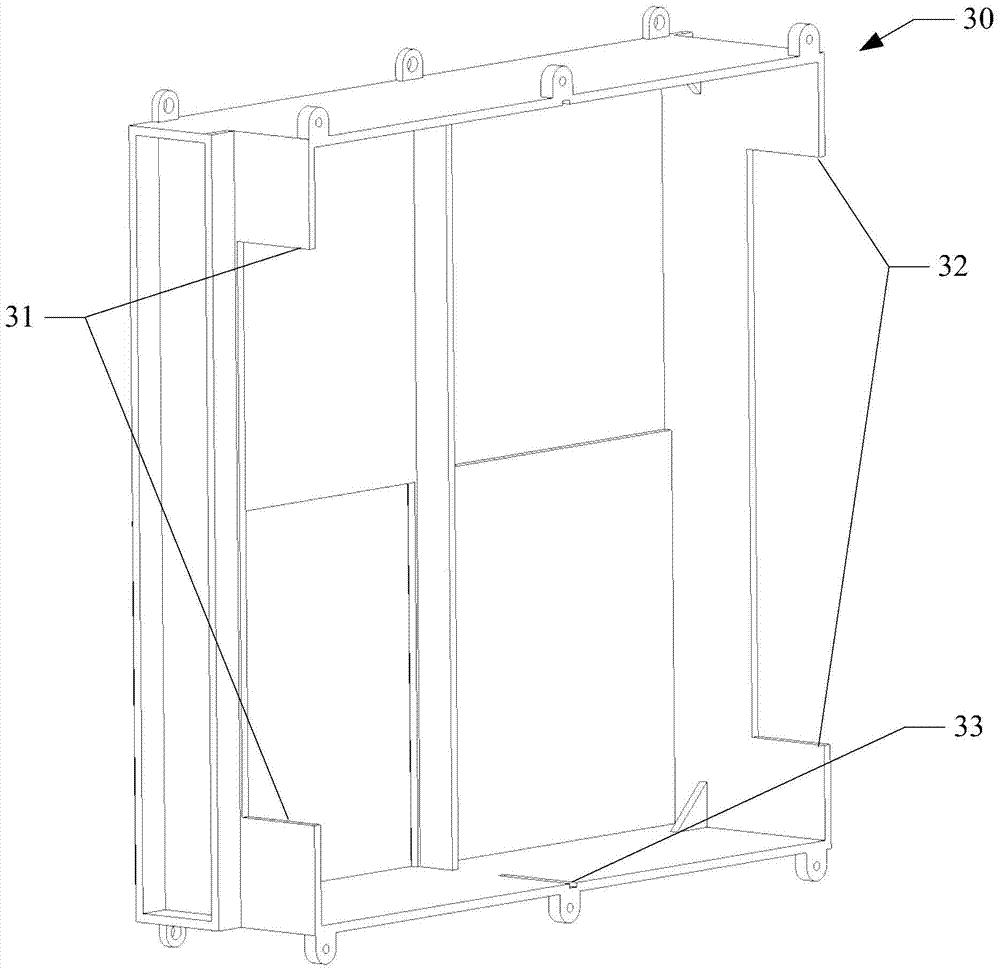
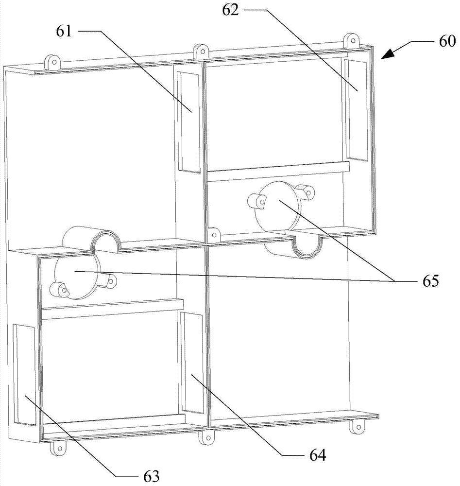
[0040] refer to Figure 1 to Figure 12 , figure 1 It is a schematic diagram of an explosion structure of an anhydrous humidification device of the present invention; figure 2 It is a structural schematic diagram of a fixed frame in an anhydrous humidification device of the present invention; image 3 It is a structural schematic diagram of the base in the anhydrous humidification device of the present invention; Figure 4 It is a structural schematic diagram of an angle of the first reversing block in the anhydrous humidification device of the present invention; Figure 5 It is a structural schemati...


PUM


Abstract

The invention discloses water-freehumidifying equipment and an air conditioning system. The water-freehumidifying equipment comprises inner and outer air blowers and a humidity-accumulating and humidifying switching device, wherein the humidity-accumulating and humidifying switching device comprises an upper sealing cover, a humidity-accumulating block, a fixed frame, a first reversingassembly, a second reversing assembly and a base, wherein a first frame body and a second frame body are arranged on the base; positions, corresponding tothe first frame body and the second frame body, ofthe bottom plate of the fixed frame arearranged in a hollow-out mode; the upper sealing cover is fixedly connected onto the fixed frame; and the upper sealing cover comprises a cover plate and a baffle plate. According to the technical scheme adopted by the invention, the water-freehumidifying equipment is simple in structure and low in cost; the two sets of reversing assemblies which are mechanically switched can be adopted to realize that humidification is carried out in one air path while humidity accumulation is carried out in the other air path; humidifying and humidity-accumulating can be simultaneously carried out by virtue of the use of the same humidity-accumulating block, the position of the humidity-accumulating block is not required to exchange, and gas tightness of the water-freehumidifying equipment is improved, thereby enabling the humidity-accumulating block to sufficiently absorb humidity and evaporate moisture, improving the humidifying amount of water-freehumidifying and the comfort of an air conditioner.

Description

technical field [0001] The invention relates to the technical field of air conditioning, in particular to a waterless humidifying device and an air conditioning system. Background technique [0002] For a long time, in order to improve the comfort of the air conditioner, competitors in the production of air conditioners have added the function of anhydrous humidification when the air conditioner is cooling or heating, but after market research, the humidity storage and humidification effect of anhydrous humidification cannot reach The expected effect generally shows that the amount of water produced during the process of storage and humidification of anhydrous humidification is insufficient, resulting in an inconspicuous amount of anhydrous humidification. In addition, in order to continuously realize the anhydrous humidification function of the air conditioner, it is often necessary to manually replace the storage. Wet block or adjust the position of the moisture storage bl...

Claims


Application Information

Patent Timeline
Patent Type & Authority Patents(China)
IPC IPC(8): F24F3/14
CPCF24F3/14
Inventor 张惟张桃
Owner MIDEA GRP CO LTD
Learn More