Coaxiality detection method

A detection method and coaxiality technology, which is applied in the detection field, can solve the problems of low measurement accuracy of the coaxiality detection method and low precision of the coaxiality error value, so as to ensure accuracy, high precision, and overcome cumulative errors Effect

Active Publication Date: 2015-10-28
NEWAY VALVE SUZHOU
View PDF4 Cites 11 Cited by
  • Summary
  • Abstract
  • Description
  • Claims
  • Application Information

AI Technical Summary

Problems solved by technology

[0005] Therefore, the technical problem to be solved by the present invention lies in the defect that the measurement accuracy of the coaxiality detection method in the prior art is not high, thereby providing a coaxiality detection method with high measurement accuracy
[0006] The further technical problem to be solved by the present invention is to overcome the defect of low accuracy of the coaxiality error value measured by the coaxiality detection method in the prior art, thereby providing a coaxiality detection method with high precision for measuring the coaxiality error

Method used


Image

  • Coaxiality detection method
  • Coaxiality detection method
  • Coaxiality detection method

Examples


Embodiment 1

[0041] This embodiment provides a coaxiality detection method, comprising the following steps:

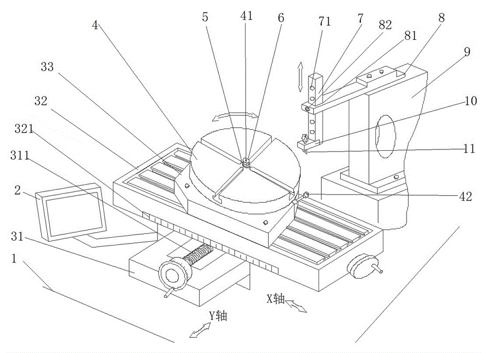
[0042] S1: Set one end hole of the standard workpiece on the rotating shaft 41, and make the probe of the measuring gauge 11 and the inner wall of the other end hole of the standard workpiece measure the circle P 0 Measuring point contact on a certain circle;

[0043] Observe the pointer pointing of measuring table 11, if the pointer of measuring table 11 points to the zero position, it means that rotating shaft 41 is parallel to the axis of measuring table 11 in the vertical direction. At this time, take off the standard workpiece and complete the calibration of rotating shaft 41; The pointer of measuring table 11 points to deviate from the zero position, then adjust the horizontal and / or vertical position of rotating shaft 41 by adjusting device, take off standard workpiece when the pointer of measuring table 11 points to zero position, complete the correction of rotating shaft 4...

Embodiment 2

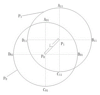
[0064] This embodiment provides a coaxiality detection method, the difference from Embodiment 1 is: for the measurement circle P of the standard workpiece 0 , and the measuring circle P of the workpiece to be detected 1 The measurement points above are all four measurement points, two of which are two ends distributed on the diameter of the measurement circle in the horizontal direction, and the other two measurement points are two ends distributed on the diameter of the measurement circle in the vertical direction.

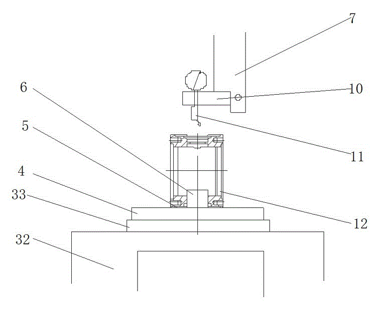
[0065] For example, when measuring the coaxiality error of the valve stem holes at both ends of the valve body 12, the assembly diagram of the valve body 12 installed on the inner hole expander 6 is as follows: figure 2 shown. First, the axis of the rotating shaft 41 of the standard workpiece in the vertical direction is calibrated, as image 3 As shown in the standard workpiece measurement circle P 0 The four measurement points on the same circumference of t...


PUM


Abstract

The present invention discloses a coaxiality detection method. The coaxiality detection method is characterized in that a standard workpiece corrects an axis of a rotating shaft, so that a pointer of a measurement instrument points to a zero; after the rotating shaft is corrected, the position coordinate of a probe is used as a detection reference point, and the position of the probe is fixed and constant; an end hole of a to-be-detected workpiece sleeves on the rotating shaft, the inner wall of the other end of the to-be-detected workpiece is contacted with the probe of which the position is fixed and constant via an adjusting device, and the pointer of the measurement instrument is observed whether to point to the zero; if the pointer points to the zero, the situation that the two end holes of the to-be-detected workpiece are coaxial is indicated; if the pointer deviates the zero, the situation that the two end holes of the to-be-detected workpiece exist a coaxiality error is indicated. During the measurement process, if the pointer of the measurement instrument points to the zero, the two end holes of the to-be-detected workpiece are coaxial, and the whole detection step is simple and is easy to operate. The measurement instrument probe is contacted with the inner wall of the other end hole of the to-be-detected workpiece directly, so that the pointing accuracy of the pointer of the measurement instrument is guaranteed, the whole detection method is high in accuracy, and an accumulated error is small.

Description

technical field [0001] The invention relates to the technical field of detection, in particular to a coaxiality detection method. Background technique [0002] At present, people usually use a three-coordinate measuring instrument for coaxiality detection, that is, measure multiple cross-sectional circles on the measured element and the reference element, and then form a 3D straight line with the centers of these circles as a common axis, and then respectively Calculate the coaxiality of the reference circular hole and the measured circular hole to the common axis, and take the maximum value as the coaxiality of the part. However, this type of instrument is expensive, and the parts of the instrument are easily damaged during use, and the maintenance cost is high. During the measurement process, it is necessary to measure multiple cross-sections and determine the common axis, so that the measurement efficiency is not high; if the number of measured cross-sections is not large...

Claims


Application Information

Patent Timeline
IPC IPC(8): G01B5/252
Inventor 沈志杰王冬青吴慧仙
Owner NEWAY VALVE SUZHOU
Why Eureka
Try Eureka