
Prediction method of far-field sound pressure of mechanical noise based on inverse boundary element method

An inverse boundary element and mechanical noise technology, applied in the measurement of ultrasonic/acoustic/infrasonic waves, measuring devices, special data processing applications, etc., can solve problems such as resolution limitations, high-precision calculation difficulties, and structural surface impracticalities. Measuring the effect of convenience

Active Publication Date: 2017-11-21
HARBIN ENG UNIV
View PDF3 Cites 0 Cited by
  • Summary
  • Abstract
  • Description
  • Claims
  • Application Information

AI Technical Summary

Problems solved by technology

However, since the far-field sound pressure signal records fewer evanescent waves, the resolution is limited by the wavelength
[0003] The technology of directly measuring the normal vibration velocity of the surface of the vibrating body to calculate the radiation sound pressure technology is based on the relationship between the sound power radiated by the vibrating body and the surface vibration, using the vibration signal to directly predict the radiation noise. The key to power estimation is how to determine the radiation coefficient. Since the radiation coefficient is not only related to the shape and boundary conditions of the component, but also related to the vibration frequency, it is very difficult to calculate with high precision
and cannot be implemented for complex structured surfaces

Method used


Image

  • Prediction method of far-field sound pressure of mechanical noise based on inverse boundary element method
  • Prediction method of far-field sound pressure of mechanical noise based on inverse boundary element method
  • Prediction method of far-field sound pressure of mechanical noise based on inverse boundary element method

Examples


Embodiment Construction

[0027] The present invention will be described in further detail below in conjunction with the accompanying drawings.

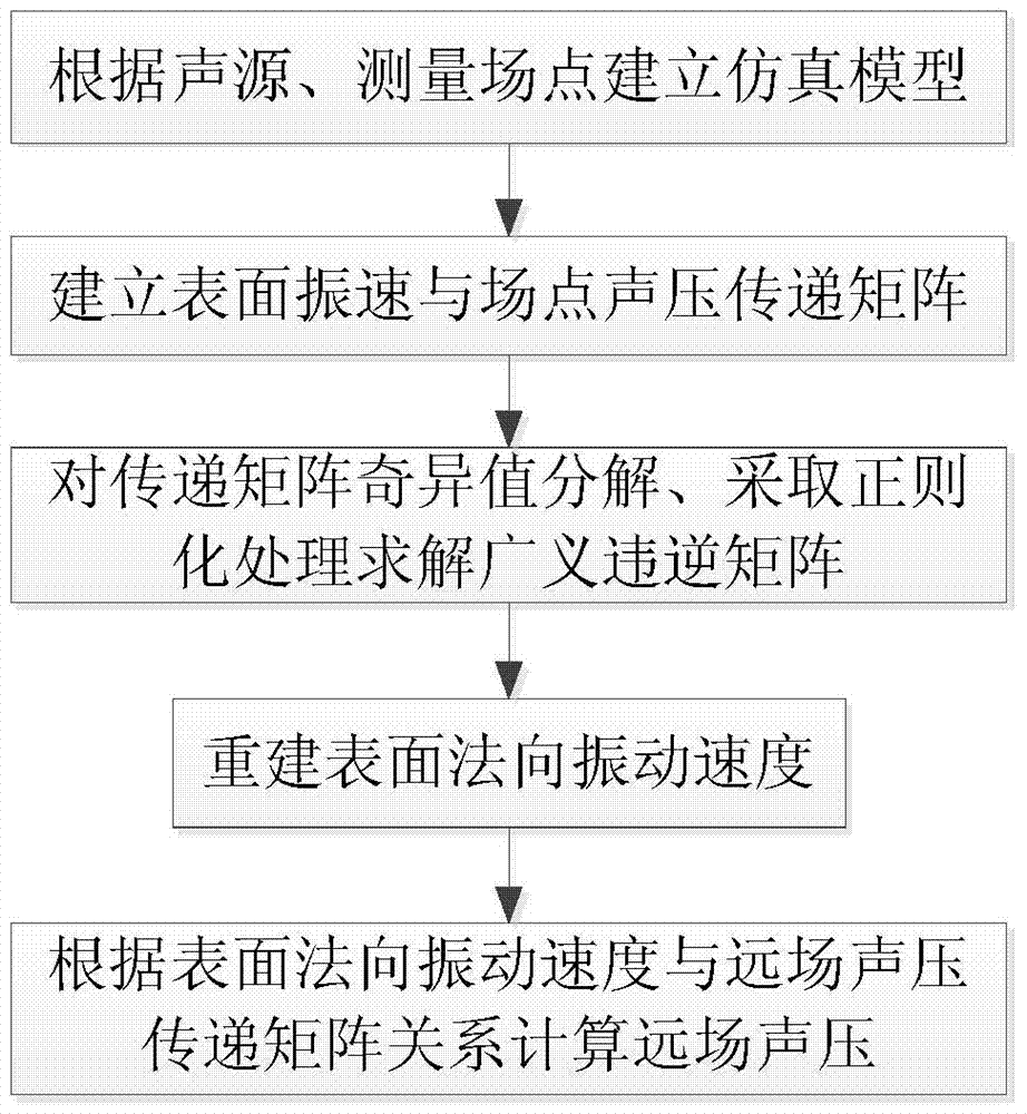
[0028] The present invention adopts the technical scheme for solving its technical problem, such as figure 1 Shown:

[0029] Step 1: Establish the simulation model of the sound source and test surface model. The grid unit of the vibration sound source model is required to be less than 1 / 6 of the wavelength corresponding to the maximum analysis frequency.

[0030] Step 2: Establish the transfer relationship matrix between the field point sound pressure and the mechanical surface vibration velocity. Establishment of Boundary Integral Equation Based on Boundary Element Method

[0031]

[0032] Among them: p(P) is the sound pressure of field point P, p(Q), v(Q) n are the surface sound pressure of the sound source and the normal vibration velocity, respectively. In order to establish the relationship between the surface sound pressure and the surface norma...


PUM


Abstract

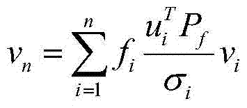
The invention discloses a mechanical noise far field sound pressure prediction method based on an inverse boundary element method, and belongs to the sound pressure prediction field. A microphone array is arranged in a wavelength of the highest analysis frequency of a target sound source, a test surface is bigger than a positive projection plane of a target sound source. One wavelength contains at least two measuring points. A reference microphone is arranged near the target sound source, and a field point complex sound pressure after cross spectrum of the microphone array and the reference microphone is obtained through measuring. a transmission relation of a field point complex sound pressure and a normal vibration speed is created based on the inverse boundary element method, and a transmission matrix is obtained. The transmission matrix is subjected to singular value decomposition, and a normal vibration speed is obtained. A far field sound pressure py is predicted according to the normal vibration speed. the relation of the far field sound pressure and the normal vibration speed is created according to a boundary integration equation, py=ATMyvn, and ATMy is the transmission matrix corresponding to the far field sound pressure. The prediction method is suitable for a surface with a complex structure and has an advantage of high precision.

Description

technical field [0001] The invention belongs to the field of sound pressure prediction, and in particular relates to a far-field sound pressure prediction method of mechanical noise based on an inverse boundary element method, which is suitable for far-field sound pressure prediction of a vibrating body with a complex structure. Background technique [0002] At present, the surface vibration velocity reconstruction method based on near-field acoustic holography technology uses the holographic data of the sound source measured close to the sound source or the vibrating surface (d<<λ), and the holographic data contains evanescent wave components that decrease exponentially with distance , so that a higher resolution can be obtained, but it requires that the measurement distance d<<λ is too harsh, which limits its application. The measurement method based on far-field acoustic holography is based on the assumption of plane waves. The sound pressure far away from the...

Claims


Application Information

Patent Timeline
Patent Type & Authority Patents(China)
IPC IPC(8): G01H17/00G06F19/00
Inventor 肖友洪吕国学季振林田新娜郑伟褚阵豪
Owner HARBIN ENG UNIV
Learn More