
In-situ Knob Calibration Device

A calibration device and knob-type technology, applied in the field of calibration instruments, can solve the problems of external loss of the calibrator and complicated operation, and achieve the effect of accurate response

Active Publication Date: 2020-02-11
安荣信科技(北京)股份有限公司
View PDF14 Cites 0 Cited by
  • Summary
  • Abstract
  • Description
  • Claims
  • Application Information

AI Technical Summary

Problems solved by technology

The disadvantage is that the operation is complicated, and the external calibrator may be lost

Method used


Image

  • In-situ Knob Calibration Device
  • In-situ Knob Calibration Device
  • In-situ Knob Calibration Device

Examples


Embodiment Construction

[0036] The present invention will be described in detail below in conjunction with the accompanying drawings.

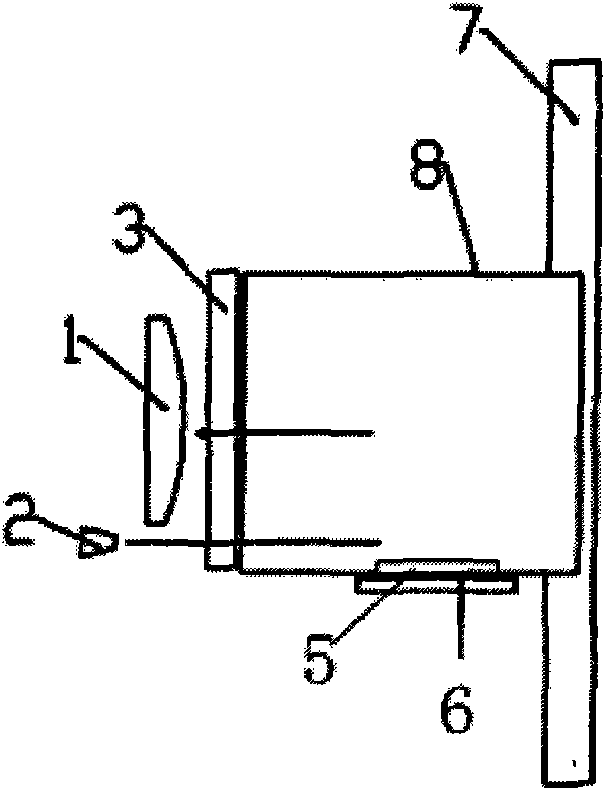
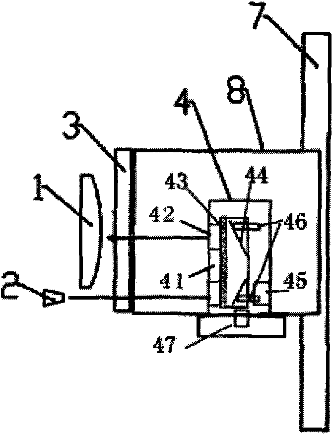
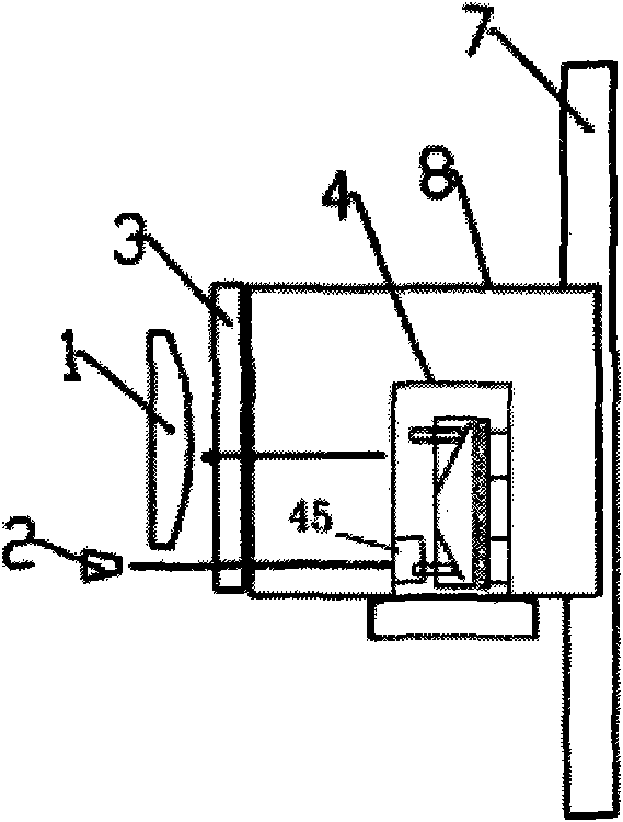
[0037] Please refer to attached Figure 4 , Figure 6 , Figure 7 , Figure 8 as shown, Figure 4It is the in-situ knob-type calibration device of the present invention, which includes a lens, a glass window, a calibrator and a calibrator frame, the calibrator is located on the calibrator frame, and the calibrator is a knob-type calibrator 111, and the knob-type calibration There is a knob 50 on the top of the calibrator 111, and the knob 50 is placed on the calibrator cover 210, and the calibrator body 202 at the lower part of the knob calibrator 111 is fixed by M2*16 screws 207, and the main part of the lower part of the knob calibrator 111 is passed through the knob 50 The rotation of the calibrator cover 210 is provided with four 3mm steel balls 209 and four springs 208, and the knob 50 provides the flexibility of rotation through four 3mm steel balls 209 and...


PUM


Abstract

The present invention relates to the field of calibration equipment of t environmental monitoring instruments, particularly to an in-situ knob type calibration apparatus. According to the present invention, the breakthrough innovation is achieved in the calibration methods, and the in-situ knob type calibration apparatus is used to overcome the problems in the prior art; the calibration apparatus is adopted as one part of the instrument, and rotates to achieve three working states such as working, part calibration and span calibration through the knob; and the in-situ knob type calibration apparatus is arranged in the instrument window lens, such that the in-situ knob type calibration apparatus is not affected by environmental pollution.

Description

technical field [0001] The invention relates to the field of calibrating instruments for environmental monitoring instruments, in particular to an in-situ knob type calibrating device. Background technique [0002] At present, the energy needed for my country's economic development mainly comes from coal combustion, and the particulate matter and sulfur dioxide released by coal combustion are the main pollutants that lead to the deterioration of the atmospheric environment. The particle concentration monitor is an essential instrument in environmental monitoring, which can provide fast, reliable and accurate quantitative smoke and dust emission data to the environmental supervision department. According to the technical requirements HJ / T75-2007 and HJ / T76-2007 of the environmental protection department, in order to ensure the accuracy of the monitoring instrument itself, it is necessary to calibrate the instrument. [0003] Such as the published patent CN200820139944.7, the...

Claims


Application Information

Patent Timeline
Patent Type & Authority Patents(China)
IPC IPC(8): G01N15/06
Inventor 杜永强曹志成朱泽恩
Owner 安荣信科技(北京)股份有限公司
Learn More