Anti-glare film, polarizing plate, liquid crystal panel, and image display device

An anti-glare film and anti-glare layer technology, which is applied in the fields of liquid crystal panels and image display devices, polarizers, and anti-glare films, can solve the problems of reduced contrast and glare, and achieve good black color sense and good anti-glare effects

Active Publication Date: 2015-10-28
DAI NIPPON PRINTING CO LTD
View PDF17 Cites 9 Cited by
  • Summary
  • Abstract
  • Description
  • Claims
  • Application Information

AI Technical Summary

Problems solved by technology

However, when the surface of the image display device is not only configured with an anti-glare film that does not reflect much, but also has an anti-glare film that has anti-glare properties to the extent that the reflection is not annoying, the screen image light will be absorbed by the anti-glare layer. Scattering occurs due to the uneven surface, which may cause so-called glare
In order to prevent the occurrence of glare, some people proposed to increase the haze. When the haze is increased, the glare can be prevented, but the contrast may be reduced.

Method used


Image

  • Anti-glare film, polarizing plate, liquid crystal panel, and image display device
  • Anti-glare film, polarizing plate, liquid crystal panel, and image display device
  • Anti-glare film, polarizing plate, liquid crystal panel, and image display device

Examples


no. 1 approach

[0044] Hereinafter, an antiglare film and the like according to a first embodiment of the present invention will be described with reference to the drawings. First of all, in this specification, terms such as "film", "sheet", and "plate" cannot be distinguished from each other only based on the difference in names. Therefore, for example, a "film" is a concept that also includes a member that can also be called a sheet or a plate. As a specific example, the "anti-glare film" also includes members called "anti-glare sheet" or "anti-glare plate". In addition, in this specification, a "weight average molecular weight" is the value obtained by dissolving in solvents, such as tetrahydrofuran (THF), and carrying out polystyrene conversion by the conventionally well-known gel permeation chromatography (GPC) method.

[0045] >>

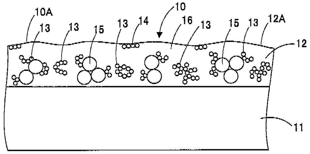
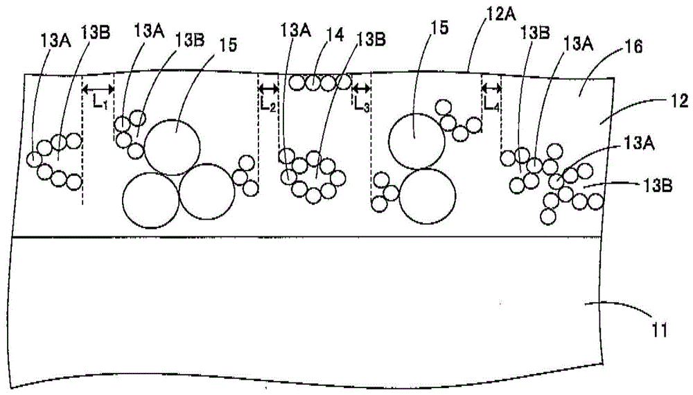
[0046] figure 1 It is a schematic structural diagram of the anti-glare film of this embodiment, figure 2 for figure 1Enlarged view of part of . Such a...

no. 2 approach

[0175] Next, an antiglare film according to a second embodiment of the present invention will be described with reference to the drawings. It should be noted that, unless otherwise specified, the content overlapping with the first embodiment will be omitted. Image 6 is a schematic configuration diagram of another anti-glare film according to this embodiment, Figure 7 for Image 6 Enlarged view of part of .

[0176] >>

[0177] Such as Image 6 As shown, the antiglare film 50 includes at least a translucent substrate 51 and an antiglare layer 52 provided on the translucent substrate 51 . Since the translucent base material 51 is the same as the translucent base material 11 described in the first embodiment, description thereof will be omitted in this embodiment.

[0178] >

[0179] The antiglare layer 52 includes a first inorganic fine particle aggregate 53 formed by aggregating three or more inorganic fine particles, a second inorganic fine particle aggregate 54 formed...

no. 3 approach

[0201] Next, an antiglare film according to a third embodiment of the present invention will be described with reference to the drawings.

[0202] >>

[0203] Figure 8 It is a schematic structural diagram of the anti-glare film of this embodiment, Figure 9 for Figure 8 Partial enlarged view of Figure 10 for Figure 9 Partial enlarged view of Figure 11 It is a schematic diagram showing the mode of measuring the clarity of the transmitted image of the anti-glare film according to the present embodiment with a transmission image clarity measuring device.

[0204] Such as Figure 8 As shown, the anti-glare film 60 includes a light-transmitting base material 61 and an anti-glare layer 62 provided on the light-transmitting base material 61 and having a concave-convex surface 62A.

[0205] The surface 60A of the anti-glare film 60 forms an uneven surface. In this embodiment, since no functional layer such as a low-refractive index layer is provided on the anti-glare laye...


PUM

PropertyMeasurementUnit
particle sizeaaaaaaaaaa
thicknessaaaaaaaaaa
thicknessaaaaaaaaaa

Abstract

The invention relates to an anti-glare film, a polarizing plate, a liquid crystal panel, and an image display device, and aims at providing an anti-glare film, a polarizing plate, a liquid crystal panel, and an image display device which have the anti-glare performance that people do not mind incident light, and has good anti-blinding performance and good black colour feeling. An anti-glare film (10) is provided with a light-transmitting base material (11) and an anti-glare layer (12) arranged on the light-transmitting base material (11). The surface of the anti-glare layer (12) is an uneven surface (12A); the anti-glare layer (12) comprises adhesive resin (16) and more than two first inorganic particle condensates (13), each first inorganic particle condensate (13) is arranged in the adhesive resin (16), and is condensed by more than three inorganic particles; each first inorganic particle condensate (13) comprises a bending part (13A), the inorganic particles are connected to form the bending part (13A), and the bending part (13A) is provided with an inside area (13B) which is filled with the adhesive resin (16).

Description

【Technical field】 [0001] The invention relates to an anti-glare film, a polarizer, a liquid crystal panel and an image display device. 【Background technique】 [0002] On the image display surface of image display devices such as liquid crystal display (LCD), cathode line tube display (CRT), plasma display (PDP), electroluminescence display (ELD), field emission display (FED), etc., Generally, in order to suppress the reflection of the observer and the background of the observer, etc., an anti-glare film with unevenness on the surface, or an anti-reflection film with an anti-reflection layer on the outermost surface (for example, refer to Japanese Patent Laid-Open No. 2011-215515 Bulletin). [0003] The antiglare film mainly includes a translucent substrate and an antiglare layer having a concave-convex surface provided on the translucent substrate. The anti-glare film scatters external light on the concave-convex surface of the anti-glare layer, and suppresses reflection o...

Claims


Application Information

Patent Timeline
Patent Type & Authority Applications(China)
IPC IPC(8): G02B5/02G02F1/1335
CPCG02F1/133502G02B1/11G02B5/0242G02B5/0294G02B5/305B32B27/08
Inventor 古井玄本田诚
Owner DAI NIPPON PRINTING CO LTD
Why Eureka
Try Eureka