Surface fitting and scissors foot supported key switch device

A scissor foot and key switch technology, applied in the direction of electric switches, electrical components, contact operating parts, etc., can solve the problems of key caps, support plate precision loss, thin sheet cannot be processed, and affect the keyboard, etc., to achieve low key height , Reduce material costs, improve the effect of matching accuracy

Active Publication Date: 2015-10-28
陈峰
View PDF5 Cites 7 Cited by
  • Summary
  • Abstract
  • Description
  • Claims
  • Application Information

AI Technical Summary

Problems solved by technology

[0023] 1. The matching part and the lower matching part of the scissors foot support 16 are formed by punching sheet metal to form a square boss, and the corners of the square boss are respectively matched with the matching parts of the keycap and the support plate. The keycap 1 The corner of the boss of the mating part scissor foot support 16 will accelerate the wear of the keycap and the support plate, causing the scissor foot support, keycap, and support plate to lose their accuracy quickly
[0024] 2. The corner of the boss with a square cross-section is chamfered----it can be inverted into a straight face, a circular arc surface, and an inverted arc surface. The chamfering process of sheet metal is more difficult (especially for thinner metal plates ), and there are poor chamfering accuracy and poor surface finish
[0026] 4. When the scissor foot support 16 adopts a thinner metal plate (such as a metal plate of 0.08mm---0.15mm), the space between the upper sliding part 6 of the scissors between the key undercut mating surface 3c and the key mating plane 3b cannot be injected production (see figure 1 -- Figure 5 The key

Method used


Image

  • Surface fitting and scissors foot supported key switch device
  • Surface fitting and scissors foot supported key switch device
  • Surface fitting and scissors foot supported key switch device

Examples


Embodiment 1

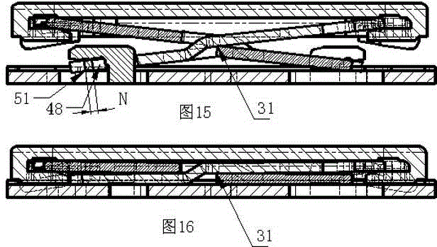
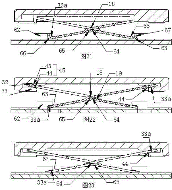
[0121] see Figure 8 -- Figure 14 , a kind of scissor foot support of the present invention is supported and the key switch device of keycap face-to-face cooperation, comprises keycap,, elastic body, membrane switch piece, the supporting plate that has matching part, the scissor foot support that has upper and lower matching part, scissor foot The support is connected to the keycap and the supporting plate by rotating or slidingly through the upper and lower matching parts. The scissor foot support forms a synchronous linkage support structure through the transmission of force between each other to ensure that the keycap moves up and down parallel to the support plate. The concave bottom surface 30 has a key matching convex shoulder 32, and the key matching convex shoulder 32 and the key undercut boss 33 of the key cap constitute the matching part of the key cap; , 44 forms below the upper end plate of the scissors.

[0122] The scissors foot support 16 is connected in rota...

Embodiment 2

[0175] see Figure 17 , Figure 18 1. On the bottom surface of the concave bottom surface of the keycap between the two matching parts in the width direction of the keycap 1, a left and right rigid key limiting boss 55 and a left and right two key fitting part bosses 57 are respectively arranged, Wherein the key-limiting boss 55 is located at the middle position between the two sections of key fitting bosses 57, and the fitting parts of the key limiting boss 55, the key fitting boss 57, and the keycap 1 are all arranged along the width direction.

[0176] The keycap anti-off structure is made of key spacing boss 55, and key spacing boss 55 inner side limiting boss guides the surface 56, and key spacing boss 55 outside is provided with key spacing boss end 58.

[0177] The key fitting portion boss 57 protrudes upwards from the bottom surface of the concave bottom surface of the keycap to form a square boss, and the corners on the outside of the boss 57 of the key fitting porti...

Embodiment 3

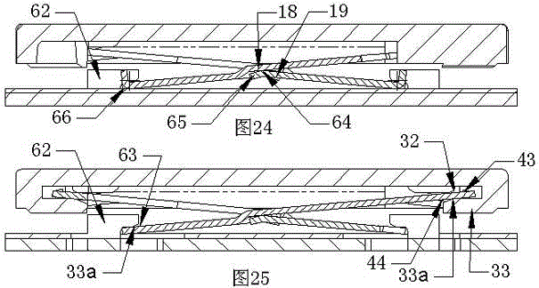
[0196] see Figure 32 1. The scissors support 16 is an inverted eight shape, and the lower matching part of the scissors support 16 is composed of the scissors lower support part, the scissors lower end upper plate surface 63 of the scissors support 16, and the scissors anti-off structure; the scissors The lower support part of the scissors of the foot support 16 and the anti-off structure of the scissors are all located on the lower plate surface 66 of the lower end of the scissors; The undercut fit arc 33a of the snap fit portion fits.

[0197] On the support plate 15 there is a stamping boss that limits the horizontal movement of the lower support portion of the scissors, and the concave surface 72 of the support plate is formed on the support plate 15 by stamping the stamping boss. The scissors lower end lower plate surface 66 of the scissors foot support 16 is bent and formed (that is, the lower end of the scissors support arc) and the support plate lower concave surface...


PUM


Abstract

The present invention discloses a surface fitting and scissors foot supported key switch device. The surface fitting and scissors foot supported key switch device comprises a keycap, an elastomer, a switch loop having a switch contact, a supporting plate having a matching part, and a scissors foot support having the upper and lower matching parts. The scissors foot support is in rotatable or slip connection with the keycap and the matching part of the support plate respectively via the upper and lower matching parts and forms a synchronous linkage supporting structure by the mutual force transmission, thereby guaranteeing that the keycap does the elevating motion parallel with the supporting plate. The surface fitting and scissors foot supported key switch device is characterized in that a concave bottom surface in the keycap is equipped with the key matching protruding shoulder 32, the key matching protruding shoulder 32 and a key inverted buckling boss 33 of the keycap form a matching part of the keycap, and the upper matching part of the scissors foot support is composed of a scissors upper end upper plate surface 43 and a scissors upper end plate lower surface 44. If the problems that the wear resistance of the scissors foot support, the keycap and the supporting plate can be improved and a thinner metal plate can be used to produce the scissors foot support to simultaneously reduce the material cost and the height of a keyboard further, can be solved, a conventional sheet metal scissors foot support can substitute for a conventional widely used plastic scissors foot support.

Description

[0001] Priority Statement: [0002] Claims 1, 7, 12-15 of the present invention, claims 42-46 of the invention patent application with application number 2014101569946 submitted to the State Intellectual Property Office of China on April 18, 2014, and the priority of the corresponding embodiments; [0003] Claims 2, 6, 7, 12-15 of the present invention, claim 15-18 of the invention patent application submitted to the State Intellectual Property Office of China on August 4, 2014 with the application number 2014103786124 and the priority of the corresponding embodiments ; [0004] Claims 3-16 of the present invention, claiming the priority of claims 61-84 and corresponding embodiments of the invention patent application with application number 2014105022929 submitted to the State Intellectual Property Office of China on September 27, 2014; [0005] Claims 3-16 of the present invention require the priority of claims 61-86 and corresponding embodiments of the invention patent appli...

Claims


Application Information

Patent Timeline
IPC IPC(8): H01H13/705H01H3/12
Inventor 陈峰
Owner 陈峰
Why Eureka
Try Eureka