Pneumatic conveying installation

A technology of pneumatic conveying and conveying equipment, which can be used in applications, tobacco, cigarette manufacturing, etc., and can solve the problem of high power consumption

Inactive Publication Date: 2015-10-28
RIEDEL FILTERTECHNIK GMBH
View PDF7 Cites 7 Cited by
  • Summary
  • Abstract
  • Description
  • Claims
  • Application Information

AI Technical Summary

Problems solved by technology

As a result, the electrical energy consumption of the conveyor is higher than necessary

Method used


Image

  • Pneumatic conveying installation

Examples


Embodiment Construction

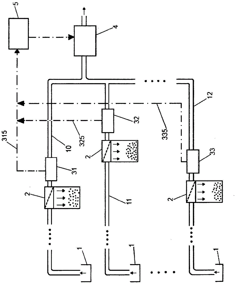
[0015] The drawing shows in a block diagram the essential components of a pneumatic conveying device according to the invention, in particular a shredded tobacco conveying device.

[0016] A plurality of conveying lines 10 , 11 , 12 are provided, which are each supplied with conveying material in the supply region 1 . Integrated in the conveying lines 10 , 11 , 12 are separating devices 2 which separate the conveying material, in particular shredded tobacco, from the conveying air. In order to generate a pressure drop, a common compressor (collectively referred to as a conveying device) 4 is arranged downstream of the conveying lines 10 , 11 , 12 . The device shown is designed as a suction conveyor device, but a pressure conveyor arranged upstream of the separating device 2 can also be operated according to the invention.

[0017] Downstream of the separating devices 2 , a regulating unit 31 , 32 , 33 is arranged in each case, which regulates a throttle device (not shown in d...


PUM


Abstract

Disclosed is a pneumatic conveying installation, in particular a cut tobacco conveying installation, for conveying a material to be conveyed, in particular cut tobacco, in a gas stream, comprising a plurality of conveying lines (10, 11, 12) that are filled with material to be conveyed in the gas stream, in particular the air steam, and comprising at least one separating device (2) for each of the conveying lines (10, 11, 12). The separating device (2) is integrated into each of the conveying lines (10, 11, 12) and is designed so as to separate the material to be conveyed and to further conduct the remaining gas stream that has been substantially separated from the material to be conveyed in the conveying line. A regulation unit (31, 32, 33) is arranged downstream of each separating device (2) in the conveying line, which regulation unit comprises and regulates a throttle device so as to set a predefined conveying speed in the respective conveying line (10, 11, 12) by setting a throttle level above or equal to a predefined minimum value (Rmin), wherein the conveying installation has a common conveying device for conveying the material to be conveyed through the conveying lines (10, 11, 12). The conveying installation comprises a control and regulation device (5), which communicates with the conveying device (4) and which is designed to record the momentary throttle levels of the throttle devices and to vary the conveying power of the conveying device (4). The control and regulation device (5) is further designed to vary the conveying power of the conveying device (4) such that the throttle level of at least one throttle device lies, in each case, in the range of the minimum throttle level (Rmin).

Description

technical field [0001] The invention relates to a pneumatic conveying device according to the preamble of claim 1 and a method for operating a pneumatic conveying device according to the preamble of claim 5 . Background technique [0002] This conveying device is mainly used for conveying shredded tobacco. This conveying usually takes place in the form of a suction conveying through the pipeline by means of a downstream compressor (in particular a fan) which generates a pressure difference in the pipeline system. In general, other conveying devices in pressure or suction mode can also be used. The air, and thus the conveyed material, is moved in the pipe system by a pressure difference between the material inlet at which the material enters the conveying line and a separator arranged in the conveying line for separating the conveying air from the conveying material. The conveying material is separated from the air flow on the separator. Usually, the compressor generates a...

Claims


Application Information

Patent Timeline
Patent Type & Authority Applications(China)
IPC IPC(8): A24C5/39
CPCA24C5/392
Inventor U·屈肯肖纳
Owner RIEDEL FILTERTECHNIK GMBH
Why Eureka
Try Eureka