Method and device for changing hole positions of drill jig

A technology for drilling holes and hole positions, which is used in boring/drilling, drilling/drilling equipment, drilling dies for workpieces, etc.

Active Publication Date: 2015-11-04
HARBIN
View PDF5 Cites 2 Cited by
  • Summary
  • Abstract
  • Description
  • Claims
  • Application Information

AI Technical Summary

Problems solved by technology

This method needs to disassemble the drilling template, remove other p...

Method used


Image

  • Method and device for changing hole positions of drill jig
  • Method and device for changing hole positions of drill jig
  • Method and device for changing hole positions of drill jig

Examples


Embodiment Construction

[0021] The method for changing the drill hole position of the present invention is described in detail below:

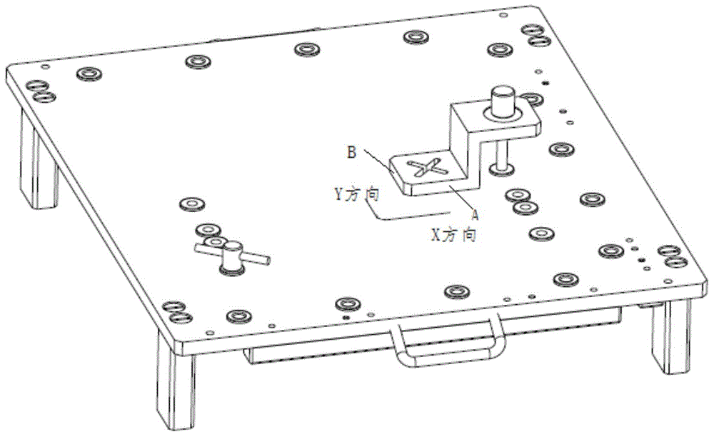
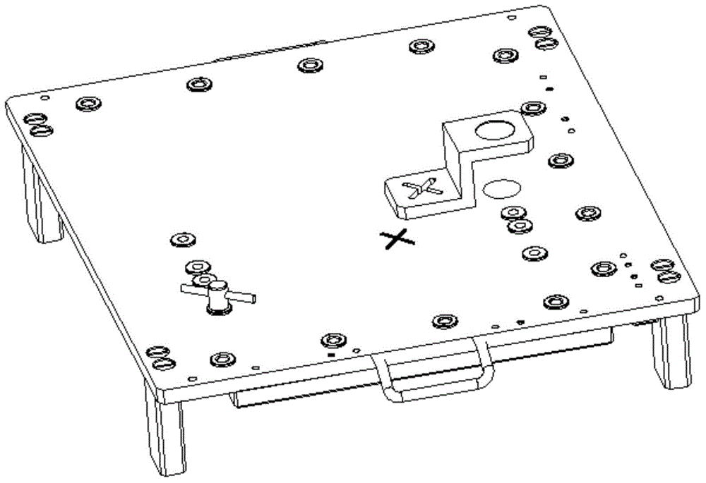
[0022] The drill template is inlaid with a drill sleeve with an outer diameter of Φ12 and an inner diameter of Φ6. figure 1 and figure 2 , Calculate the deviation value of the hole position of the drill sleeve: calculate the horizontal deviation value and the vertical deviation value of the new drill sleeve hole position and the old drill sleeve hole position, in this embodiment, the coordinates of the old hole position Φ12 hole X=100mm, Y=100mm , the coordinates of the new Φ12 hole are X=104mm, Y=103mm, the calculated lateral deviation of the new Φ12 hole and the old Φ12 hole is 4mm, and the longitudinal deviation is 3mm;

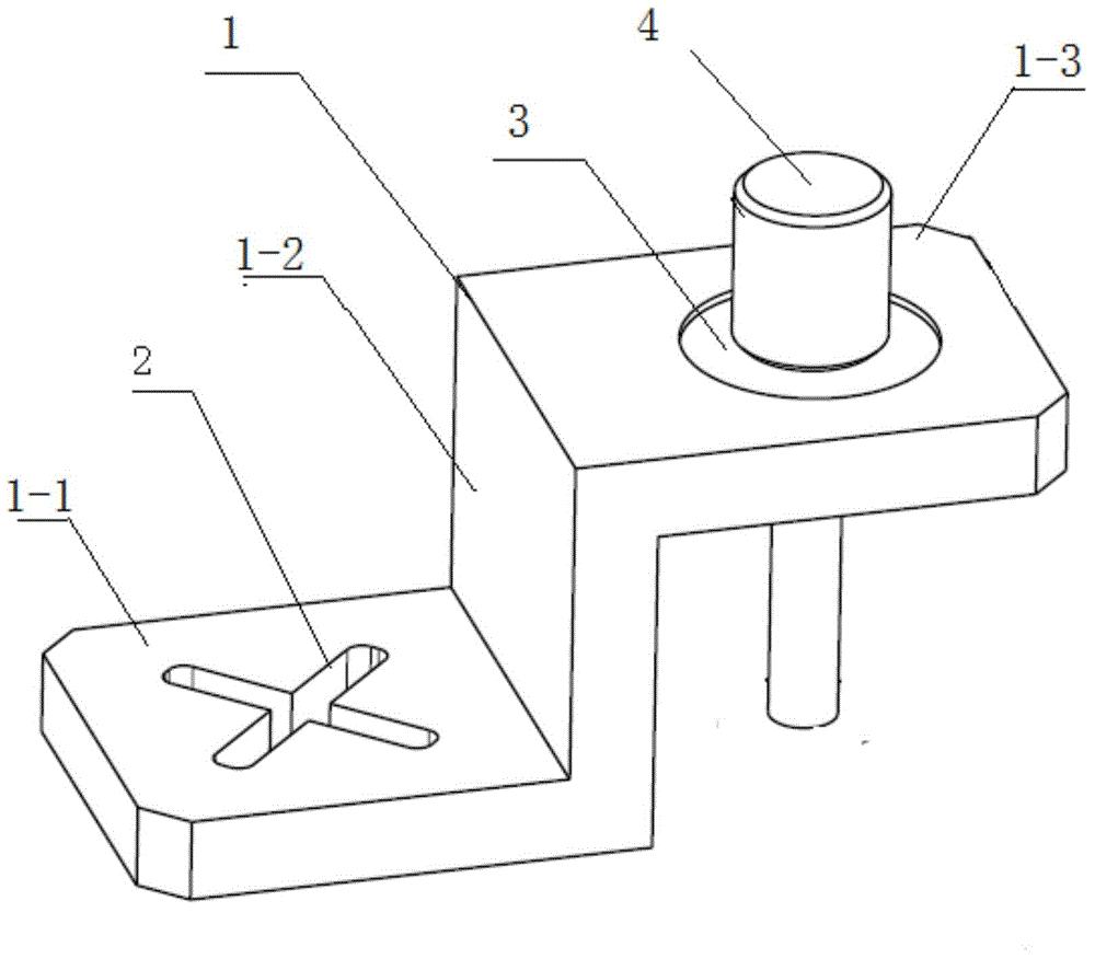
[0023] refer to figure 2 and image 3 Connect the positioning hole of the hole position transfer device with the old hole position through the positioning pin 4, and determine the horizontal positioning reference plane A and the longitudinal...


PUM


Abstract

The invention provides a method for changing the hole positions of a drill jig. The method includes the steps that a deviation value of the position of a drill bushing hole is calculated; a transverse deviation value and a longitudinal deviation value between the position of a new drill bushing hole and the position of an old drill bushing hole are calculated; a positioning hole of a hole position transferring device is connected with the position of the old drill bushing hole through a positioning pin (4), and the directions of a transverse positioning base level and a longitudinal positioning base level of the hole position transferring device are determined according to the deviation value and the direction, determined in the step one, of the position of the drill bushing hole; and a cross-shaped groove is formed at the portion of a base plate of the hole position transferring device, 45-degree angles or 90-degree angles are formed between two through grooves of the cross-shaped groove and the transverse positioning base level and the longitudinal positioning base level of the hole position transferring device, a cross-shaped line is marked in the cross-shaped groove, an intersection point of the cross-shaped line is determined, and the positioning pin (4) is taken out from the positioning hole.

Description

technical field [0001] The invention relates to the hole position processing field of an aircraft floor drilling mold. Background technique [0002] The large-scale floor drilling mold of the aircraft is composed of many drill sleeves, and the holes of the drill sleeves are all machined by CNC machine tools and assembled on the drill mold body after the bushes are inlaid. The position of these drill bushing holes needs to be modified due to design changes, and the drill bushing hole positions on many drill templates need to be modified. The traditional method is to use the CNC machine tool to align the new hole shape and then enlarge the hole. This method needs to disassemble the drilling template, remove other parts on the drilling template, and take the drilling template for processing. Contents of the invention [0003] The technical problem to be solved in the present invention: [0004] A method for correcting the deviation hole position without dismantling the dri...

Claims


Application Information

Patent Timeline
IPC IPC(8): B23B47/28B23B41/00G06F19/00
Inventor 李野花宏亮乔恩慧黄兴刘征宇云庆文
Owner HARBIN
Why Eureka
Try Eureka