Draining device for underwater friction stitch welding

A drainage device, friction stitch welding technology, applied in welding equipment, non-electric welding equipment, metal processing equipment and other directions, can solve problems such as poor welding quality

Active Publication Date: 2015-11-04
天津益饶科技孵化有限公司
View PDF9 Cites 0 Cited by
  • Summary
  • Abstract
  • Description
  • Claims
  • Application Information

AI Technical Summary

Problems solved by technology

[0005] The purpose of the present invention is to overcome the deficiencies of the prior art and provide a local drainage device for underwater friction stitch welding. In order to solve the problem of

Method used


Image

  • Draining device for underwater friction stitch welding

Examples


Example Embodiment

[0016] The technical solution of the present invention will be further described below in conjunction with specific embodiments.
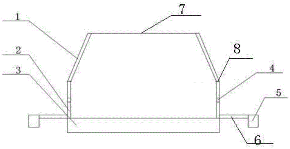
[0017] As attached figure 1 As shown, the structural diagram of the drainage device of the present invention, where 1 is a flexible shell, 2 is a flange, 3 is a sponge gasket, 4 is a vent hole, 5 is a magnetic suction cup, 6 is a backing plate, 7 is a mounting hole, and 8 To connect the clamp.

[0018] The flexible shell, flange, sponge liner and the surface of the workpiece constitute an air chamber, which is mainly used for drainage and sealing of the welding area, and also includes a matching gas delivery device (not shown in the figure).

[0019] The flexible shell is in the shape of a conical cylinder. At the uppermost end of the entire device, a mounting hole is provided in the center of the top of the flexible shell for connecting and sealing the spindle head of the welding equipment. The lower end surface of the flexible shell is connected with t...


PUM


Abstract

The invention discloses a draining device for underwater friction stitch welding. A flexible outer shell is in a conical cylinder shape, and a mounting hole is formed in the position, located at the uppermost end of the whole device, of the center of the top end of the flexible outer shell; the lower end face of the flexible outer shell is connected with a flange, and the flange is in a circular-ring shape; the upper end face of the flexible outer shell is fixedly connected with the lower end face of the flexible outer shell; air inlet holes are evenly formed along the circumference of the flange, and the lower end face of the flange is fixedly connected with a circular-ring foam mat; magnetic suction cups are connected with base plates, and the base plates are connected to the bottom of the flange; and the number of the magnetic suction cups is with the same as the number of the base plates, and the magnetic suction cups are evenly distributed in the circumferential direction of the flange. The problems that the underwater friction stitch welding quality is poor, and air environment needs to be built underwater for welding are solved; and the aims of optimizing an underwater welding working procedure and expanding the range of technological parameters are achieved.

Description

technical field [0001] The invention belongs to the technical field of solid-phase welding, and more specifically relates to a novel friction stitch welding local dry drainage device. Background technique [0002] Friction stitch welding is a new type of solid phase joining method. Friction stitch welding was invented in 1992 by TWI's W M Thomas, E D Nicholas et al. In the past ten years, Europe has invested a lot of energy in related basic research. Domestically, Beijing Institute of Petrochemical Technology and Tianjin University have done preliminary research on friction stitch welding. [0003] The unit hole welding of friction stitch welding is called Friction Hydro Pillar Processing (FHPP). Its principle is to use the consumable characteristic rod (which can be called the stopper rod) to drive the stopper rod through the driving device Rotate, the stopper rod descends while rotating, and the stopper rod contacts and rubs against the plug hole (the hole to be welded)...

Claims


Application Information

Patent Timeline
IPC IPC(8): B23K20/26B23K20/12
CPCB23K20/12B23K20/122B23K20/26
Inventor 贺钧王志江崔雷邓彩艳王东坡
Owner 天津益饶科技孵化有限公司
Why Eureka
Try Eureka