Humidity detection and moisturizing control method and system for large-volume concrete

A technology for mass concrete and humidity detection, applied in humidity control, control/regulation system, non-electric variable control, etc., can solve the problems of water replenishment timing and poor control accuracy of water replenishment, and achieve accurate water replenishment timing, good effect and precision. high effect

Active Publication Date: 2015-11-04
ZHENGZHOU SHUANGJIE TECH CO LTD
View PDF10 Cites 8 Cited by
  • Summary
  • Abstract
  • Description
  • Claims
  • Application Information

AI Technical Summary

Problems solved by technology

[0006] The purpose of the present invention is to provide a method and system suitable for the precise control of moisture retention in the mass concrete construction process in view of the problem of mainly relying on manual experience to judge water replenishment in the current mass concrete construction process, and the poor control accuracy of water replenishment timing and water replenishment amount

Method used


Image

  • Humidity detection and moisturizing control method and system for large-volume concrete
  • Humidity detection and moisturizing control method and system for large-volume concrete

Examples


Embodiment 1

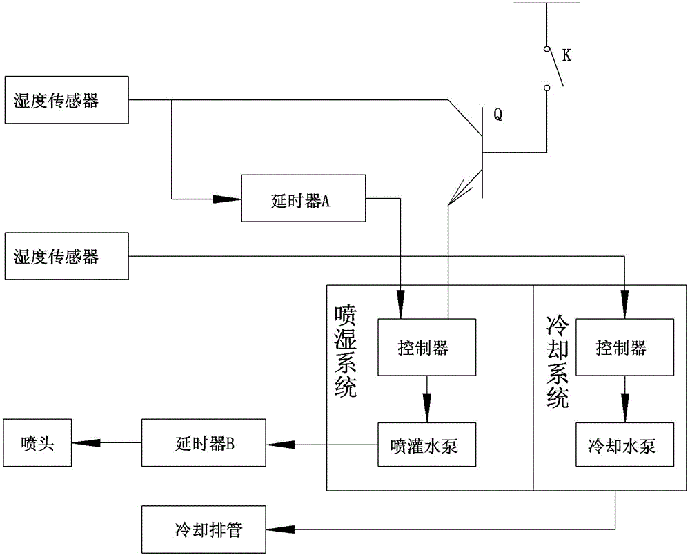
[0018] Embodiment 1: A large-volume concrete humidity detection and moisture control method. A humidity sensor is arranged on the surface of the constructed concrete, and the humidity sensor is used to detect whether the humidity of the surface area of ​​the constructed concrete meets the humidity standard range. If it is less than the lower limit of the humidity standard range When the value is d1, the humidity sensor sends a water replenishment signal to the controller of the spraying system, and the controller controls the spraying system to spray water at a fixed time or quantity; and, a delayer A is set, and the delayer A is in the delay range T A Inside, the controller of the spraying system does not accept any signal from the humidity sensor; the spraying system stops spraying water after meeting the timing or quantitative water spraying requirements; the delayer A is in the delay range T A In addition, when the humidity sensor detects that the humidity in the surface ar...

Embodiment 2

[0023] Embodiment 2: a kind of mass concrete humidity, temperature The detection and moisture control method, on the basis of Embodiment 1, is equipped with a temperature sensor together with the humidity sensor, and a cooling pipe is arranged in the mass concrete. When the value of the temperature sensor rises to a critical value, the cooling system drives cooling water into the cooling pipe. Circulate in the tube and cool down.

Embodiment 3

[0024] Embodiment 3: see figure 1 , a large-volume concrete humidity detection and moisture control system. A humidity sensor is arranged on the surface of the constructed concrete. The humidity sensor is connected to the signal input terminal of the controller of the spraying system through the delayer A, and the output terminal of the controller of the spraying system is connected to the signal input terminal of the spraying system. The water pump is connected, and the delay device B is set on the water pump at the same time.


PUM


Abstract

The invention discloses a humidity detection and moisturizing control method and system for large-volume concrete. A humidity detector is arranged on a constructed concrete surface layer; the humidity sensor is connected with a signal input end of a controller of a spray system through a time delayer A; an output end of the controller of the spray system is connected with a water pump or a fan; besides, a time delayer B or a flow meter is arranged on the water pump or the fan. The system disclosed by the invention can realize an automatic detection and spray moisturizing function, and can overcome the defect that concrete is artificially moisturized through experience at present; through the adoption of the system disclosed by the invention, time and labor are saved; the moisturizing time is accurate; the precision of water supply amount is high; the moisturizing effect is good. T time delayer A and the time delayer B are arranged, so that the misjudgment of the sensor can be avoided, the degree of automation is high, and manual work is not needed.

Description

technical field [0001] The invention belongs to the technical field of temperature and humidity testing of concrete structures, and in particular relates to a method and system capable of detecting the temperature and humidity of concrete structures and controlling moisture retention. Background technique [0002] Mass concrete is mainly used in important projects such as hydropower plants, nuclear power plants, culverts, bridges, etc. Its volume is huge (as little as hundreds of cubic meters, and as many as hundreds of thousands of cubic meters), and its quality requirements are very strict. At present, for the detection of the performance of large-volume concrete, the concrete specimens are tested in the laboratory at the same time, and the pre-curing of the specimens is set at a constant temperature. "Hydraulic Concrete Test Regulations" (SL352-2006) stipulates that the standard curing temperature of the specimen should be controlled at 20°C ± 5°C; there is even a patente...

Claims


Application Information

Patent Timeline
Patent Type & Authority Applications(China)
IPC IPC(8): E01D21/00E02D15/02E04G21/24G01D21/02G05D22/02
Inventor 魏鲁双
Owner ZHENGZHOU SHUANGJIE TECH CO LTD
Why Eureka
Try Eureka