

Sealing structure for cable outgoing hole of electric device
An electrical device and cable outlet technology, applied in the direction of pipes, pipes/pipe joints/pipes, mechanical equipment, etc., can solve the problems of poor sealing effect at the cable outlet, damage to internal electrical components, loss of function of electrical devices, etc. Excellent waterproof effect, improved sealing degree and novel structure
- Summary
- Abstract
- Description
- Claims
- Application Information
AI Technical Summary
Problems solved by technology
Method used
Image

Examples
Embodiment 1
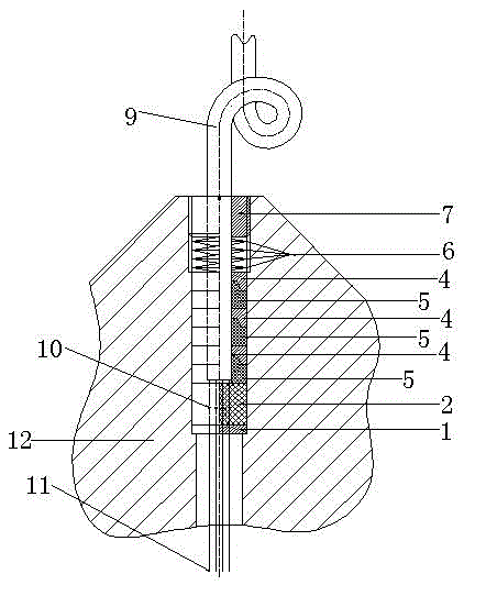
[0015] Example 1 as figure 1 As shown, this embodiment provides a sealing structure for the cable outlet hole of an electrical device. The cable outlet hole sealing structure includes an insulating gasket 1 with several small holes, a cable lug rubber bollard 2 with several small holes, Several special-shaped metal pressure rings 4 with round holes in the middle, several special-shaped rubber sealing rings 5 with round holes in the middle, several spring washers 6 with round holes in the middle, and hollow compression rings with round holes in the middle Screw plug 7, the above-mentioned components are installed in the outlet hole of electrical device 12 in the following order: firstly, the internal wire 11 of electrical device 12 passes through the small hole in insulating washer 1 through insulating washer 1, and then passes through the hole in the rubber bollard 2 of the cable lug. The small hole passes through the rubber bollard 2 of the cable lug, and then the hollow co...
Embodiment 2
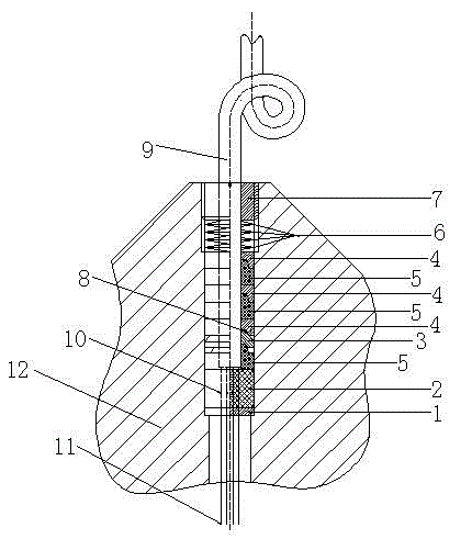
[0016] Example 2 as figure 2 As shown, in order to meet the sealing requirements of the cable hole with shielding layer, the cable outlet hole sealing structure also includes a cable shielding layer metal pressure plate 3 with a round hole in the middle, the insulating gasket 1 and the cable lug rubber cover There are multiple threading holes in the middle of the column 2. The metal pressure plate 3 of the cable shielding layer, the special-shaped metal pressure ring 4, the special-shaped rubber sealing ring 5, the spring washer 6 and the hollow compression plug 7 are all ring-shaped. The order of installing the above components in the outlet hole of the electrical device is as follows: firstly, the internal wire 11 of the electrical device 12 passes through the insulating washer 1 through the small hole in the insulating washer 1, and then passes through the hole in the rubber bollard 2 of the cable lug. The small hole passes through the rubber bollard 2 of the cable lug, an...
PUM
 Abstract
Description
Claims
Application Information