Test interface structure

A technology of test interface and side opening, which is applied in the direction of pipes/pipe joints/fittings, connections with fluid cut-off devices, passing components, etc., which can solve the problems of cumbersome structure of the test interface and poor sealing performance, and achieve simple structure and improved performance. The effect of long service life and low assembly difficulty

Inactive Publication Date: 2016-04-20
STATE GRID SHANDONG ELECTRIC POWER +1
View PDF6 Cites 3 Cited by
  • Summary
  • Abstract
  • Description
  • Claims
  • Application Information

AI Technical Summary

Problems solved by technology

[0005] Therefore, the technical problem to be solved by the present invention is to overcome the technical defects of the cumbersome test interface structure and poor sealing performance in the prior art, thereby providing a test interface structure with a simple structure and good sealing performance

Method used


Image

  • Test interface structure
  • Test interface structure
  • Test interface structure

Examples


Embodiment

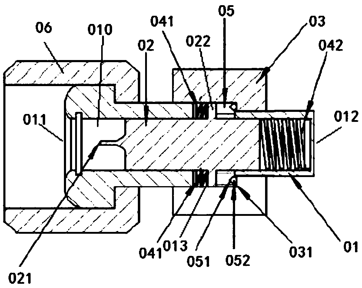
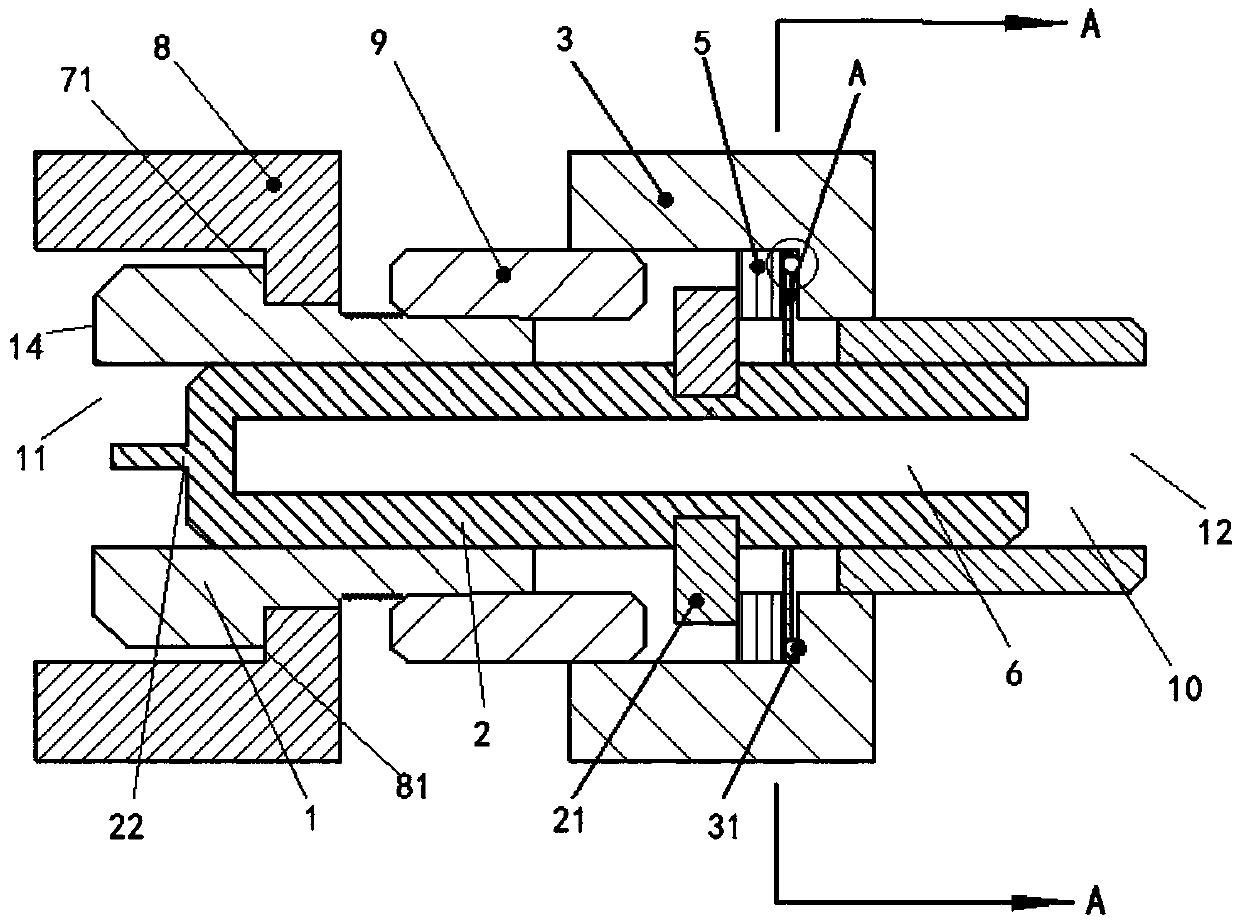
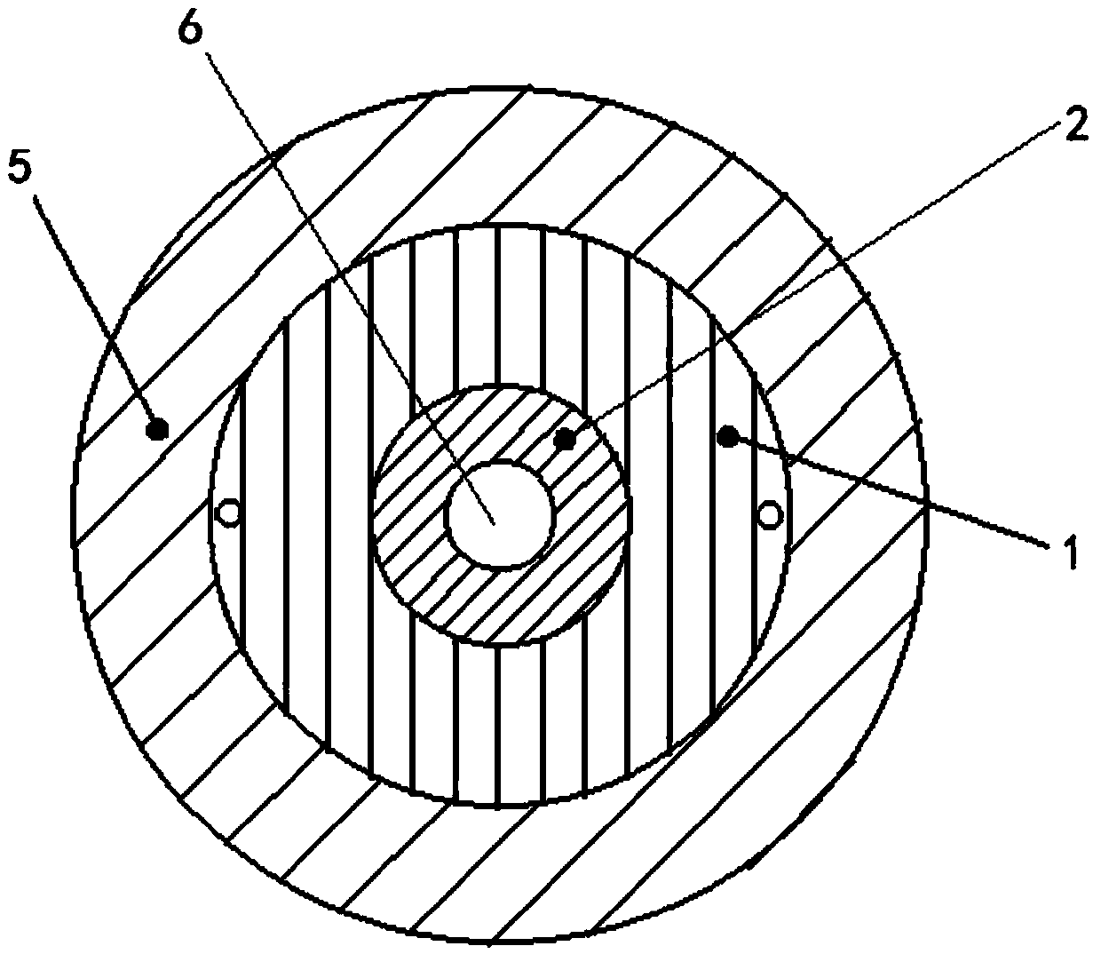
[0044] This embodiment provides a test interface structure, such as Figure 2-3 As shown, it includes: a valve body 1 with an inner cavity 10, the inner cavity 10 has a first opening 11 for communicating with a check valve, and a second opening 12 for communicating with a test device; a valve core 2, It is movably installed inside the inner chamber 10, has a thimble 22, and has a first plug inserted into the inside of the check valve to open the check valve, so that the second opening 12 communicates with the check valve. One position, and withdrawn from the inside of the check valve to close the check valve, so that the second opening 12 is cut off from the check valve and communicated with the second position; the strip through hole 13 is at least one, It is set on the outer wall of the valve body 1 and communicates with the inner cavity 10; at least one pushing part 21 is arranged on the valve core 2 and extends out of the valve core 2 through the long through hole 13. The...


PUM


Abstract

The invention provides a test interface structure which comprises a valve, a valve element, at least one elongated through hole, at least one pushing portion, a driving member and a wear-resistant structure. The valve has an inner cavity which is provided with a first opening communicated with a check valve, and a second opening communicated with test equipment, the valve element is movably mounted inside the inner cavity and can be at a first position abutting inside the check valve to enable the second opening to be communicated with the check valve and a second position extracting from the inside of the check valve to enable communication between the second opening and the check valve to be cut off, the elongated through holes are formed in the outer side wall of the valve and communicated with the inner cavity, the pushing portions are arranged on the valve element and extend out of the same through the elongated through holes, the driving member sleeves the outer wall of the valve in a threaded manner and can move axially along the valve rotatably and is provided with a driving portion used for driving the pushing portions, and the wear-resistant structure is arranged between the driving portion and the pushing portions and used for converting spiral extrusion driving of the driving portion to the pushing portions into axial extrusion driving. The test interface structure is compact in structure and high in sealability.

Description

technical field [0001] The invention relates to the technical field of gas testing interfaces, in particular to a testing interface structure. Background technique [0002] Most of the current inflatable equipment (such as SF 6 The interface of inflatable equipment) adopts spring type check valve structure. The spring check valve can effectively prevent the leakage of gas in the gas chamber. In order to test the gas moisture content and gas components of the inflatable equipment, in the prior art, the test interface is generally screwed onto the spring-type check valve. During the rotation, the internal thimble gradually pushes away the spring-type check valve. Valve spool, once the external thread advances in place, the spool will be fully opened. At this time, the micro-water content of the gas in the gas chamber can be measured and the gas decomposition products can be analyzed through the connected test pipeline, pressure reducing valve, tester, etc. After the test is...

Claims


Application Information

Patent Timeline
Patent Type & Authority Applications(China)
IPC IPC(8): F16L29/02
CPCF16L29/02
Inventor 尹玉娟刘鹏刘杰雷敏吴寿山孙昭昌曹晓华谭波
Owner STATE GRID SHANDONG ELECTRIC POWER
Why Eureka
Try Eureka