Pipe joint monitored by utilizing computer

A technology of computer monitoring and pipe joints, which is applied in the field of pipe joints, can solve problems such as the trouble of replacing pipes, affecting residents' water use, and waste of water sources, and achieves the goal of improving the degree of fixing, improving the degree of sealing and fixing effect, and improving the degree of sealing and fixing effect Effect

Active Publication Date: 2021-01-26
YANTAI ENG & TECH COLLEGE YANTAI TECHNICIAN INST
View PDF7 Cites 3 Cited by
  • Summary
  • Abstract
  • Description
  • Claims
  • Application Information

AI Technical Summary

Problems solved by technology

[0008] When working, in the prior art, most of the connection methods between pipes are hot-melt or threaded connection. Although the hot-melt method can solve the problem of pipe sealing, it is more troublesome when replacing the pipe. The sealing performance is poor. At the same time, when there is water leakage in the long-distance water supply pipeline, the staff cannot quickly detect the water leakage of the pipeline, and at the same time, they cannot quickly and accurately find out the location of the pipeline leakage, which causes the problem of waste of water resources. At the same time, It will affect the water consumption of residents. The pipe joints made by the present invention abandon the traditional pipes and use hot-melt connection to connect the pipes. By setting the ring layer, the sealing degree between the pipes and the pipe joints can be improved. A pressure measuring rod is installed in the pipe joint of each pipe, and the pressure of the water flow in the pipe joint can be monitored in real time, so that the pipe connected to each pipe joint can be monitored. When the pipe leaks, the pressure of the water flow in the pipe joint will be reduced, so that the water can be stopped to prevent waste caused by excessive water outflow. The leaking pipe can be quickly located according to the locator in the pipe joint, so that the pipeline can be quickly and accurately repaired to prevent excessive water outflow from causing waste. Waste; when using the pipe joint made by the present invention, at first the pipe joint of the present invention is installed at the joint of each pipeline, when installing the pipeline, at first the pipe body is inserted in the first annular groove on both sides of the fixed pipe, During the insertion process of the tube body, the annular block in the first chute will be squeezed. When the annular block is squeezed, the gas in the first chute will be pressed into the first air bag. When the first air bag is inflated It will squeeze the pipe body, so as to improve the sealing degree between the fixed pipe and the pipe body, and then rotate the threaded ring on the pipe body, because the threaded ring and the thread on the outer surface of the fixed pipe mesh with each other, so that the pipe can be fixed through the threaded ring. The body is fixed on the fixed pipe. In this process, the degree of fixing between the pipe body and the fixed pipe can be improved, thereby preventing the pipe body from falling off. When the connected pipe starts to pass water, the water flowing into the second annular groove will flow to the Push the leaking plate on the right to the left, and most of the water will flow out from the tapered groove on the leaking plate until it flows into the next pipe. When the pressure of the water flow in the pipe is constant, the sliding distance of the right leaking plate is also Relatively constant, during the sliding process of the right leaking plate, the pulling rope moving to the left at this time will be wound on the take-up roller, and then the controller judges the pressure of the water flow in the pipe according to the distance of the pull rope wound on the take-up roller, Feedback to the computer, when the pipe body leaks, the water flow pressure on the right leaking plate will decrease, so that the distance of the right leaking plate moving to the left will be reduced. At this time, the take-up roller detects the distance of the winding rope When it decreases, it will be fed back to the computer, and at the same time, the controller controls the first motor in a connector in front of the connector to rotate. During the rotation of the first motor, the pull rope will be wound, thereby driving the right leaking plate to move to the left and It fits with the left bushing plate, and at the same time, the controller controls the second motor to rotate, and drives the left bushing plate to rotate 30 degrees. When the left motor rotates 30 degrees, the left bushing plate and the right bushing plate will The tapered grooves are staggered to seal off the fixed tube and prevent leaking The pipeline is sealed to prevent excessive water leakage from causing waste. When the computer detects water leakage from the pipe body, it will locate it through the locator and notify the water plant to stop discharging water, thereby preventing the explosion of the pipeline due to excessive water pressure in other pipelines. Since the right bushing plate is fixedly connected with an elastic telescopic pressure measuring rod, and the other end of the pressure measuring rod is attached to the left bushing plate, the pressure measuring rod will be squeezed during the sliding process of the right bushing plate, so that the pressure measuring rod In a relatively balanced state, the pressure of the water flow can be measured more accurately during this process, thereby preventing the pipeline from leaking. At the same time, it can also prevent the two leakage plates from being pushed together when the water flow pressure is too high, so that the pull rope cannot be used. The water flow is used to measure the pressure. When the two leaking plates are attached to each other, after the left leaking plate rotates 30 degrees, the pressure measuring rod will move to the left side of the left leaking plate through the tapered groove on the left leaking plate. In this process, it can prevent the two leakage plates from being stuck together, so that the pipeline cannot be blocked and the water flow cannot be blocked.

Method used


Image

  • Pipe joint monitored by utilizing computer
  • Pipe joint monitored by utilizing computer
  • Pipe joint monitored by utilizing computer

Examples


Embodiment 1

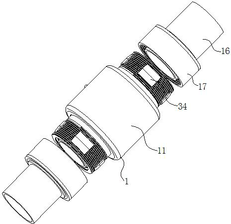
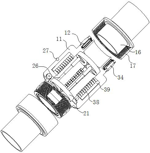
[0031] Example 1, such as Figure 1-Figure 6 As shown, a computer-monitored pipe joint according to the present invention includes a connector 1 and a pipe body 16; the connector 1 includes a fixed tube 11, and the middle part of the fixed tube 11 is designed as a protrusion; the fixed tube 11. The left and right sides of the protrusion are provided with a first annular groove 12 in the inner wall of the fixed pipe 11, and the first annular groove 12 is designed around the fixed pipe 11; the outer sides of the two first annular grooves 12 are on the outer surface of the fixed pipe 11. There are threads; both sides of the fixed pipe 11 are provided with pipe bodies 16; the outer surfaces of the two pipe bodies 16 are rotatably connected with threaded rings 17 through slip rings, and the threaded rings 17 are all connected to the surfaces of both sides of the fixed pipe 11. The threads are engaged with each other; the bottoms of the two first annular grooves 12 are provided with...

Embodiment 2

[0033] Embodiment 2, different from Embodiment 1, is that the inner walls of the two first annular grooves 12 are fixedly connected with evenly arranged annular rods 3 by short rods, and the number of annular rods 3 is two; each of the first annular The outer surfaces of the two annular rods 3 in the groove 12 are rotatably connected with an annular layer 31, and the annular layer 31 is made of rubber material; the outer surface of each annular layer 31 is fixed with a uniformly arranged first arc-shaped shaft 32;

[0034] During work, since the second annular groove 2 is rotationally connected with the annular layer 31, when the pipe body 16 is inserted into the first annular groove 12, the annular layer 31 will be pushed to rotate on the annular rod 3, and the annular layer 31 will rotate During the process, it will be attached to the outer surface of the tube body 16 and squeeze the tube body 16. In this process, the sealing degree and fixing effect between the tube body 16 ...

Embodiment 3

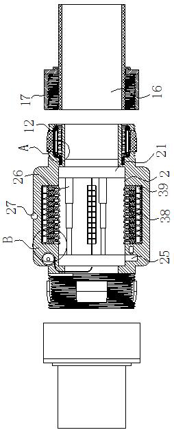
[0035] Embodiment 3 is different from Embodiment 2 in that the outer sides of the two first annular grooves 12 are provided with evenly arranged second slide grooves 33 in the inner wall of the fixed pipe 11, and the second slide grooves 33 pass through the fixed pipe 11; the second slider 34 is slidably connected to the inner wall of each second chute 33, and the side of the second slider 34 close to the tube body 16 is arc-shaped and lower than the fixed tube 11. The inner surface of each of the second sliders 34 is fixed with uniformly arranged second arc-shaped shafts 35, and the second arc-shaped shafts 35 and the first arc-shaped shafts 32 are alternately arranged;

[0036]During operation, since the side of the second slider 34 close to the pipe body 16 is designed in an arc shape, when the threaded ring 17 engages with the thread on the fixed pipe 11, it will squeeze the second slide groove 33 under the second slider 34 Slide, and extrude the annular layer 31, in this ...


PUM


Abstract

The invention belongs to the technical field of pipe joints, and particularly relates to a pipe joint monitored by utilizing a computer. The pipe joint monitored by utilizing the computer comprises aconnector and pipe bodies, the connector comprises a fixed pipe, first annular grooves are formed in positions, in the inner wall of the fixed pipe, on the end faces of the left and right sides of a bulge of the fixed pipe, threads are formed in the positions, on the outer surface of the fixing pipe, on the outer sides of the two first annular grooves, the pipe bodies are arranged on the two sidesof the fixed pipe, the outer surfaces of the two pipe bodies are rotationally connected with threaded rings through sliding rings, and first sliding grooves are formed in the groove bottoms of the two first annular grooves. The pipe joint monitored by utilizing the computer is mainly used for solving the problems that at present, when water leakage happens to all water supply pipelines which areexposed on the ground, used for conveying water to all households and connected through the pipe joint, workers cannot rapidly perceive the water leakage situation of the pipelines and cannot quicklyand accurately find out the water leakage positions of the pipelines at the same time, and therefore water source waste is caused, and meanwhile, household water consumption can further be influenced.

Description

technical field [0001] The invention belongs to the technical field of pipe joints, in particular to a pipe joint monitored by a computer. Background technique [0002] The hydraulic term refers to the parts that connect the pipelines or install the pipelines on the hydraulic components in the hydraulic system. oral style. [0003] In the use of various pipelines, rubber joints, expansion joints, force transmission joints, expansion joints, and quick joints all play a common role in the pipeline connection, that is, they play a role of expansion and compensation displacement for the operation of the pipeline. Because they have this commonality in pipeline connection, they can be complementary, interchangeable and substituted in pipeline connection. The design units and installation engineering companies mostly base on the location of the pipeline connection, whether there are fixed buttresses in the pipeline, whether there are infinite buttresses and directional limit butt...

Claims


Application Information

Patent Timeline
Patent Type & Authority Applications(China)
IPC IPC(8): F16L17/02F16L15/08F16L29/00F16K3/08F16K3/314F17D5/06
CPCF16K3/0209F16K3/0254F16K3/08F16K3/314F16L15/008F16L15/08F16L17/02F16L29/00F16L2201/30F17D5/06
Inventor 杜超李灿蔡明玉张玮马秀华
Owner YANTAI ENG & TECH COLLEGE YANTAI TECHNICIAN INST
Why Eureka
Try Eureka