
Electronic device

A technology for electronic equipment and transparent panels, which is applied in nonlinear optics, instruments, optics, etc., can solve the problems of inconvenient viewing and use of display screens, small overall size of display panels, and smaller display area ratios, etc. Reduced width and ease of use

Inactive Publication Date: 2015-11-04
GUANGDONG OPPO MOBILE TELECOMM CORP LTD
View PDF6 Cites 15 Cited by
  • Summary
  • Abstract
  • Description
  • Claims
  • Application Information

AI Technical Summary

Problems solved by technology

For example, mobile terminals such as mobile phones and tablet computers have black borders formed by ink areas around the display screen, and the black borders belong to the non-display area. Look, if the black border is wider, the width of the border becomes larger, and the proportion of the display area of ​​the transparent panel becomes smaller. Visually, the overall size of the display panel is smaller, which is not convenient for users to watch and use the display screen

Method used


Image

  • Electronic device
  • Electronic device
  • Electronic device

Examples


Embodiment Construction

[0019] In order to make the object, technical solution and advantages of the present invention clearer, the present invention will be further described in detail below in conjunction with the accompanying drawings and embodiments. It should be understood that the specific embodiments described here are only used to explain the present invention, not to limit the present invention.

[0020] It should be noted that when an element is referred to as being “fixed on” or “disposed on” another element, it may be directly on the other element or there may be an intervening element at the same time. When an element is referred to as being "connected to" another element, it can be directly connected to the other element or intervening elements may also be present.

[0021] It should also be noted that the orientation terms such as left, right, up, and down in the embodiments of the present invention are only relative concepts or refer to the normal use state of the product, and should ...


PUM

PropertyMeasurementUnit
refractive indexaaaaaaaaaa

Abstract

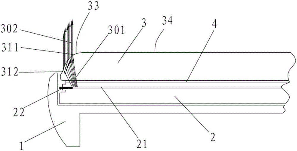
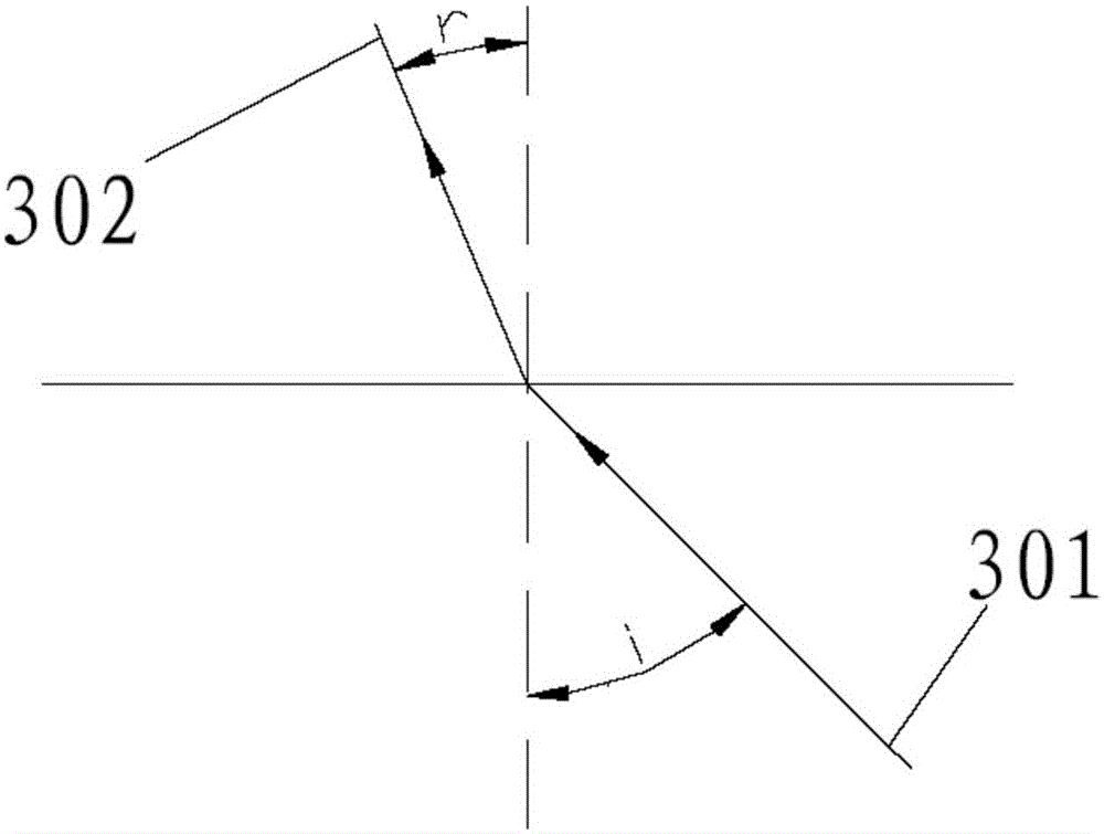
The invention is applicable to the technical field of electronic equipment, and discloses electronic equipment. The electronic equipment comprises a body, a display module and a transparent panel. The display module and the transparent panel are connected to the body. The display module comprises a display area and a non-display area positioned on the lateral side of the display area. The transparent panel covers the display area and the non-display area. A light guide structure is arranged at a position, corresponding to the upper side of the non-display area, of the transparent panel and is used for refracting light rays emitted by the display area to the outside of the transparent panel from the inside of the transparent panel. The refractive index of the transparent panel is larger than 1. The electronic equipment has the advantages that through the light guide structure used for refracting the light rays emitted by the display area to the outside of the transparent panel from the inside of the transparent panel, the light rays are emitted from the light guide structure when being observed from the visual angle of a user, so that the electronic equipment can be enabled to have an extremely narrow edge or be free of a black edge and is attractive and elegant.

Description

technical field [0001] The invention belongs to the technical field of electronic equipment, and in particular relates to an electronic equipment. Background technique [0002] At present, liquid crystal display devices have been widely used in various electronic products as display components of electronic equipment. With the development of thinner and lighter electronic products, the frame of electronic equipment is designed to be narrower and narrower. For example, mobile terminals such as mobile phones and tablet computers have black borders formed by ink areas around the display screen, and the black borders belong to the non-display area. Look, if the black border is wider, the width of the border becomes larger, and the proportion of the display area of ​​the transparent panel becomes smaller. Visually, the overall size of the display panel is smaller, which is not convenient for users to view and use the display screen. Contents of the invention [0003] The purpo...

Claims


Application Information

Patent Timeline
Patent Type & Authority Applications(China)
IPC IPC(8): G02F1/1333
CPCG02F1/133308G02F1/13332
Inventor 冉可
Owner GUANGDONG OPPO MOBILE TELECOMM CORP LTD
Learn More