Circuit protecting device

A circuit protection and electrode technology, which is applied to circuits, resistors, electrical components, etc., can solve the problems of reducing resistance limitations, increasing manufacturing costs, reducing resistance, etc., and achieves the effects of improving stability, reducing heat loss, and reducing space

Inactive Publication Date: 2015-11-04
SMART ELECTRONICS CO LTD
View PDF6 Cites 7 Cited by
  • Summary
  • Abstract
  • Description
  • Claims
  • Application Information

AI Technical Summary

Problems solved by technology

But circuit protection devices using existing NTC thermistors have limitations in reducing resistance
More specifically, in order to reduce the resistance, the size of the NTC thermistor needs to be increased. However, as the size of the thermistor increases, the manufacturing cost will also increase significantly.
Therefore, there is a limitation in reducing the resistance only by increasing the NTC thermistor

Method used


Image

  • Circuit protecting device
  • Circuit protecting device
  • Circuit protecting device

Examples


Embodiment Construction

[0051] Hereinafter, some embodiments of the present invention will be described with reference to the accompanying drawings:

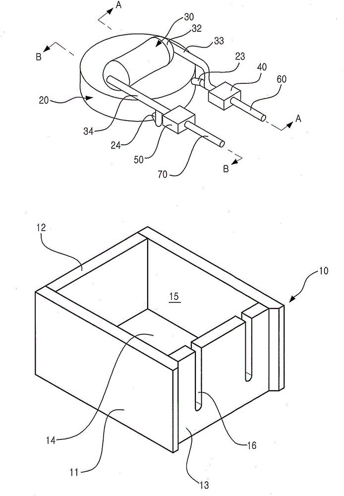
[0052] The first embodiment of the present invention includes a box 10 , a thermistor 20 and a resistance element 30 .

[0053] like figure 1 As shown, the box 10 includes a pair of side walls 11, a rear wall 12, a front wall 13, and a bottom wall 14. These elements define a receiving space 15 for accommodating the thermistor 20 and the resistance element 30, and its The top is opened. The front wall 13 is formed with a plurality of guide grooves 16 for guiding lead wires which will be described later.

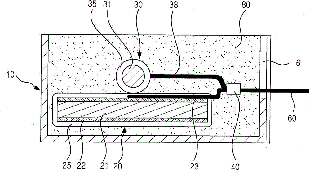
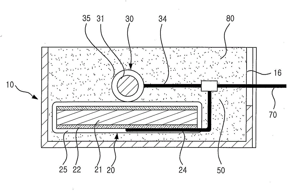
[0054] like figure 2 and image 3 As shown, the thermistor 20 includes a resistance heating element 21, a pair of electrodes 22 arranged on both sides of the resistance heating element 21, and an input line 23 and an output line 24 respectively extending from the pair of electrodes 22, these The components are all covered with a coating material ...


PUM


Abstract

A circuit protection device is disclosed. The circuit protection device includes a case (10), an NTC thermistor (20), and a resistor (30). An input line (23) of the NTC thermistor (20) is connected to an input line (33) of the resistor (30) by an input connecting part (40). An output line (24) of the NTC thermistor (20) is connected to an output line (34) of the resistor (30) by an output connecting part (50). The thermistor (20) has a planar shape. The resistor (30) has a rod shape. The resistor (30) is arranged on the center of the NTC thermistor (20). A central line of a longitudinal direction of the resistor (30) is parallel to the NTC thermistor (20). Thereby, thermal imbalance is reduced by the mutual thermal influence of the resistor and the NTC thermistor.

Description

technical field [0001] The present invention relates to a circuit protection device; in particular, the circuit protection device reduces thermal imbalance among multiple resistance heating elements by thermally influencing each other arranged inside the box. Background technique [0002] When electricity is applied to an electronic device, a large amount of current will flow instantaneously, and this current is called an inrush current (Inrush Current). When the surge current is repeatedly introduced to the circuit board mounted on the electronic device, the introduction of the surge current will cause the electronic components or semiconductor devices integrated on the circuit board to be damaged or deteriorated, resulting in shortened life or reduced function. degradation. For this reason, additional circuit protection devices need to be mounted on the circuit board. [0003] One of the well-known circuit protection devices is the thermistor. The thermistor is a resist...

Claims


Application Information

Patent Timeline
Patent Type & Authority Applications(China)
IPC IPC(8): H01C13/02
CPCH01C1/024H01C1/1413H01C1/16H01C7/04
Inventor 姜斗园金炫昌文皇帝申雅岚姜泰宪安相玟
Owner SMART ELECTRONICS CO LTD
Why Eureka
Try Eureka