
Motor vehicle door lock

A motor vehicle door lock and motion technology, applied in electric vehicle locks, vehicle locks, doors, etc., can solve the problems of weight saving and cost saving, high driving device, heavy cost, etc., and achieve weight reduction, small structure, and total cost. reduced effect

Inactive Publication Date: 2017-12-08
KIEKERT AG
View PDF7 Cites 0 Cited by
  • Summary
  • Abstract
  • Description
  • Claims
  • Application Information

AI Technical Summary

Problems solved by technology

In practice, this leads to the use of relatively large, heavy and cost-intensive drives in order to carry out the closing movement in any case
This practice is disadvantageous in terms of weight saving and cost saving

Method used


Image

  • Motor vehicle door lock
  • Motor vehicle door lock
  • Motor vehicle door lock

Examples


Embodiment Construction

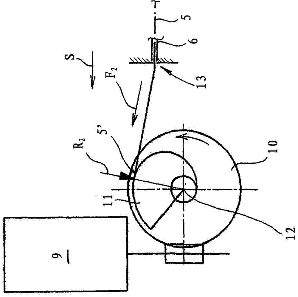
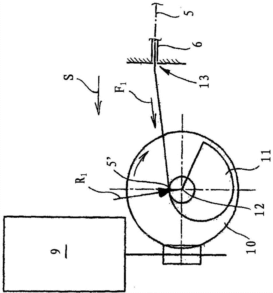
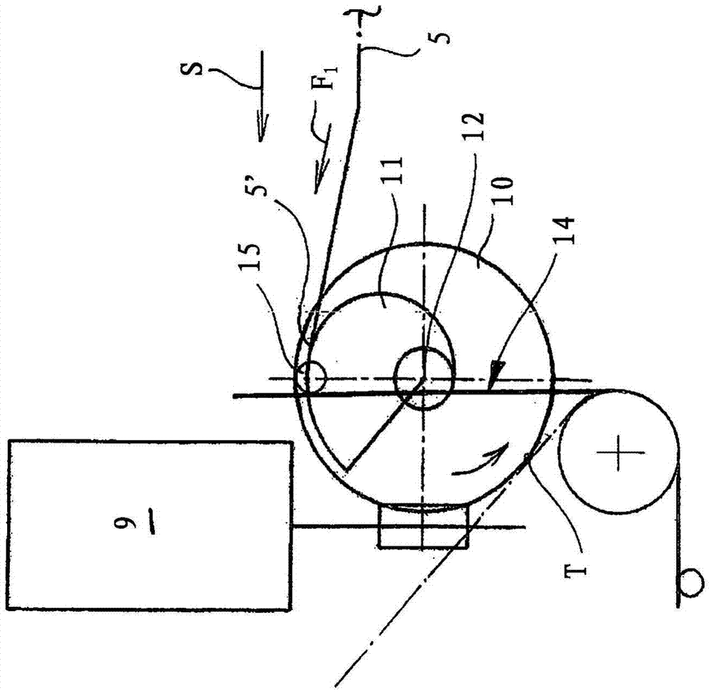
[0027] The drawing shows a motor vehicle door lock with a conventional locking device 1 , 2 comprising a rotary lock 1 and a pawl 2 . Locking device 1, 2 only in image 3 shown in . Also visible here is the closing pawl 3 , which is acted upon by the Bowden cables 5 , 6 in conjunction with the transfer rod 4 . In this exemplary embodiment, Bowden cables 5 , 6 are transmission elements 5 , 6 .

[0028] Once the Bowden cables 5, 6 or their core 5 are loaded relative to the noose 6 according to image 3 The force or closing force F pointing to the left in the illustration of the diagram, the drive pawl 3 moved to the stop 7 of the rotary locking fork 1 makes the rotary locking fork 1 move from its position image 3 Transfer from the pre-lock position shown in to the main lock position. To this end, the rotary catch 1 must be moved about its rotational axis 8 in the counterclockwise direction shown.

[0029] exist image 3The pre-clamping position shown in , corresponds to t...


PUM


Abstract

The invention relates to a motor vehicle door lock equipped with a closing / opening device (5, 6; 9, 10, 11) having a drive (9, 10, 11) and a transmission element (5, 6) . Furthermore, a locking device (1, 2) is realized. Drives (9, 10, 11) act on the closures (1, 2) with interposed transfer elements (5, 6) in order to open or close said closures. According to the invention, the drives (9, 10, 11) are designed to be variable in torque and act on the transmission elements (5, 6) with a torque that depends on the drive travel (s).

Description

technical field [0001] The invention relates to a motor vehicle door lock comprising a closing / opening device and a locking device, the closing / opening device having a drive and a transmission element, the drive acting on the locking device with the transmission element interposed to turn it off or on. Background technique [0002] Various closing devices for motor vehicle door locks are known. Thus, DE 101 40 385 A1 relates to a servo lock carrier for a motor vehicle door lock. In this case, the stop of the motor vehicle door lock is arranged on the movable actuating rocker. Furthermore, a drive for actuating the joystick is provided. The drive moves the rocker with the stop and the rotary latch including the stop and thus drives the corresponding door from the pre-locking position to the main locking position. The additional locking lever ensures that the actuating rocker is held in this position when the door is manually shifted from the pre-locking position into the ...

Claims


Application Information

Patent Timeline
Patent Type & Authority Patents(China)
IPC IPC(8): E05B79/20E05B81/20E05B81/30E05B81/40
CPCE05B79/20E05B81/20E05B81/30E05B81/42B60J5/00E05C21/00F16H25/14
Inventor C·特普费尔U·莱德曼M·舒尔茨C·斯图姆
Owner KIEKERT AG
Learn More