Eureka AIR delivers breakthrough ideas for toughest innovation challenges, trusted by R&D personnel around the world.

Gasket

a gasket and gasket technology, applied in the field of gaskets, can solve the problems of easy torsion of gaskets, lowering working efficiency, and difficult uniform conductance, and achieve the effects of reducing reaction force, satisfying insertibility, and demonstrating sealability

Inactive Publication Date: 2010-07-27
NOK CORP
View PDF18 Cites 16 Cited by
  • Summary
  • Abstract
  • Description
  • Claims
  • Application Information

AI Technical Summary

Benefits of technology

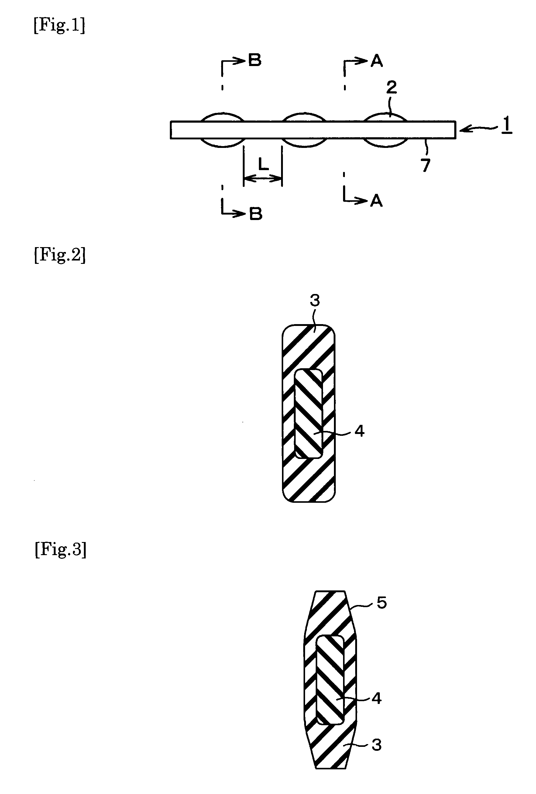
[0016]The present gasket has a low reaction force, a distinguished sealability and both bending rigidity and torsion rigidity in such degrees as to attain a satisfactory effect on insertibility. That is, the bending rigidity and torsion rigidity of the entire gasket can be improved by making the inner layer from rubber of high-hardness, thereby improving the insertibility of the gasket into a housing groove. At the same time, the sealability can be ensured by making the outer layer from rubber of low-hardness. In other words, the outer layer of low rubber hardness and the inner layer of higher rubber hardness make the compressibility of the rubber layer of the outer layer partially higher, when compressed, thereby ensuring exertion of the necessary surface pressure. That is, the present gasket comprising two rubber layers can undergo sealing at a low compressibility, as compared with the conventional gasket consisting of a single rubber layer. Furthermore, the conventional gasket consisting of a single layer has such problems as falling-down, etc., when compressed, whereas the present gasket can be prevented from abnormal falling-down, buckling, etc. of the gasket by the presence of an inner high-hardness rubber layer.
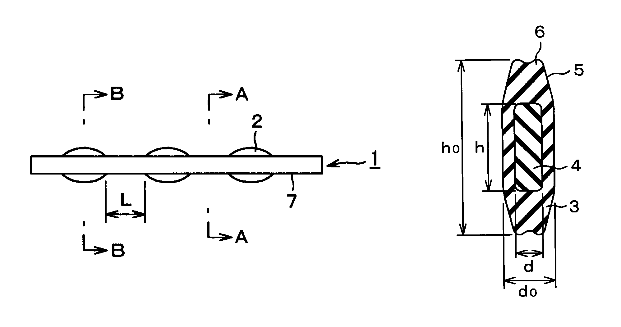
[0017]Particularly, in the longitudinal cross-section as viewed from the width direction of a gasket, a gasket having a ratio h / ho of the height h of an inner layer to the height ho of an outer layer of 0.3-0.8, and a ratio d / do of the width d of an inner layer to the width do of an outer layer of 0.5-0.8 has a low reaction force and distinguished insertibility and sealability. That is, a distortion at the boundary surface between the inner layer and the outer layer will be smaller, when compressed, by setting the hardness, dimension and shape of the outer and inner rubber layer to values in specific ranges, thereby suppressing peeling at the boundary surface and also suppressing a considerable increase in the reaction force. That is, the compression cracking of a gasket can be suppressed. Furthermore, the present gasket is also so distinguishable in the moldability that the molding can be carried out easily and precisely.

Problems solved by technology

It is desirable for making gaskets having a lower reaction force to use rubber materials of low hardness, but in the case of inserting such gaskets of relatively large type, in a shape of larger longitudinal cross-section as viewed from the width direction, and made of materials of low hardness, into grooves in engine members having various complicated shapes, the gaskets are easily susceptible to torsion in the insertion working, lowering the working efficiency, or the inserted gaskets undergo partial flexure or elongation, making it hard to conduct uniform insertion, and consequently often causing leakage at the time of compression tight sealing or compression cracking of gaskets.
In such structures, however, the frame must be molded to meet the desired dimensions of fixing member in advance, and a gasket must be integrally molded to match up with the frame, making the production process complicated.
In the case of a gasket in a three-dimensional shape, as shown in FIG. 1 of the following Patent Literature 5, integral molding of the gasket to match up with the frame is a difficult problem.
In that case, molding of the core boy in advance is a complicated problem and an exact placement of the core body at a predetermined position of the gasket cross-section, for example, at a center portion, at the time of molding, is also a difficult problem.
Furthermore, a gasket provided with a core body of high rigidity, such as metals, resins, etc. has a problem that the gasket itself has a higher reaction force, and also such further problems that a high shearing stress arises at the boundary surface between the rubber material and the core body, causing peeling to take place at the boundary surface therebetween.

Method used


Image

  • Gasket
  • Gasket
  • Gasket

Examples


example 1

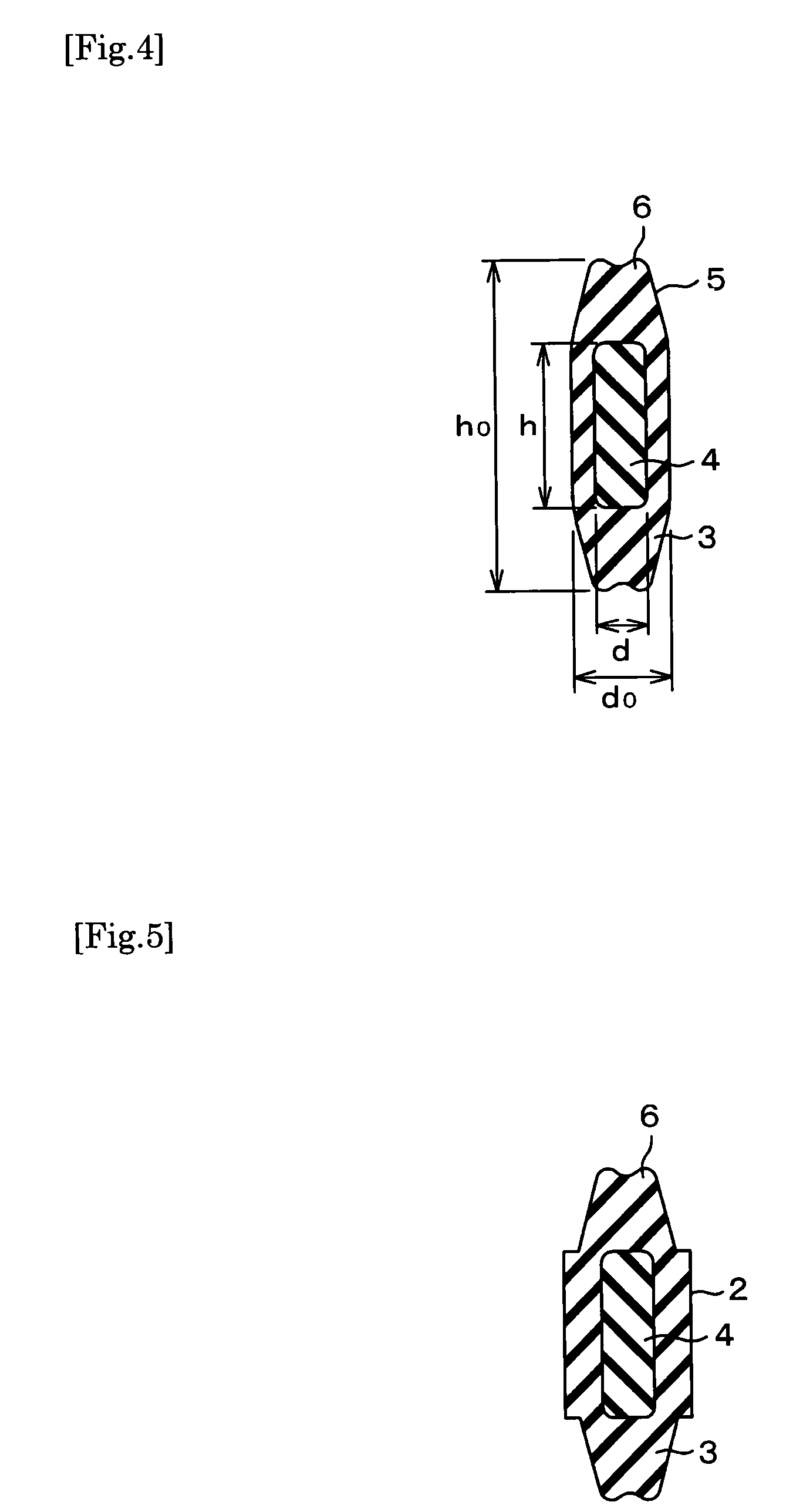
[0049]Integrated rubber gaskets in a cross-sectional shape as shown in FIG. 4, in which the outer layer was made from a low-hardness acrylic rubber having a JIS A hardness of 60, the inner layer was made from a high-hardness nitrile rubber having a JIS A hardness of 90, and the peripheral length of the annular body was set to 1 m, the height h0 of the outer layer to 8.2 mm, the width d0 of the outer layer to 2.3 mm, the height h of the inner layer to various height ratios h / h0, the width d of the inner layer to a width ratios d / d0 of 0.63, the radius of curvatures at the corners of the inner layer to 0.5 mm, the distance between the sealing projections to 0.8 mm, and the taper inclination to 13°, were compressed at a compressibility of 0.25 in the longitudinal direction to determine various characteristics.

[0050]Such various characteristics as reaction force, bending rigidity, torsion rigidity, maximum principal distortion at the boundary surface between the inner layer and the oute...

example 2

[0053]In Example 1, the height ratio h / h0 was set to 0.63, and the width ratio d / d0 was set to various ratios. Results shown in the following. Table 2 were obtained.

[0054]

TABLE 2Items of determination·Width ratio d / d0evaluation0.430.500.630.75Reaction force (N / mm)4.14.14.24.3Bending rigidity (Nmm2)35405579Torsion rigidity (Nmm2)599650750858Max. principal distortion0.410.410.390.37at boundary surface (—)Max. principal distortion (—)0.640.680.680.68InsertibilityΔΔ◯◯Sealability◯◯◯◯


PUM


Abstract

A gasket in an integrated double-layered structure comprising an outer layer and an inner layer enclosed by the outer layer, in which the outer layer is a low-hardness rubber layer having a JIS A hardness of 40-70, and the inner layer is a high-hardness rubber layer having a JIS A hardness of 80-100, where a ratio h / h0 of height h of the inner layer to height h0 of the outer layer is preferably 0.3-0.8, and ratio d / d0 of height d of the inner layer to width d0 of the outer layer is preferably 0.5-0.8 in the longitudal cross-section as view from the width direction of the gasket, has a low reaction force, and distinguished sealability and insertibility, and used as inserted between two members, one of which has a groove for insertion.

Description

RELATED APPLICATION[0001]This application is a 35 U.S.C. §371 national stage filing of International Patent Application No. PCT / JP2006 / 307805, filed Apr. 13, 2006, to which priority is claimed under 35 U.S.C. §120 and through which and to which priority is claimed to Japanese Priority Patent Application No. 2005-124518, filed Apr. 22, 2005.TECHNICAL FIELD[0002]The present invention relates to a gasket, and more particularly to a gasket with a low reaction force, and distinguished sealability and insertibility.BACKGROUND ART[0003]Relatively large types of gaskets are used for the inlet manifolds, filter blankets, cylinder head covers, etc. of automobile engines by inserting the gaskets between two members, one of which has a groove for insertion to effect tight sealing therebetween. To meet the recent trend for making the engine weight lighter, the engine members are now made from resins or aluminum, and consequently the rigidity of members becomes lower. Thus, the gaskets of a lower...

Claims


Application Information

Patent Timeline
Patent Type & Authority Patents(United States)
IPC IPC(8): F16J15/10
CPCF16J15/061F16J15/104
Inventor SUZUKI, KIYOHIROKAMEIKE, MANSHUYOSHITSUNE, SHUJINAKAO, TAKASHI
Owner NOK CORP
Why Eureka
Eureka Blog
Learn More