Battery cooling structure

a battery module and cooling structure technology, applied in the field of battery module cooling structure, can solve the problems of degrading the performance of the battery module cooling, and achieve the effects of enhancing the cooling effect reducing the thickness of the battery module, and efficient transfer of the heat of the battery modul

Active Publication Date: 2014-12-18
HONDA MOTOR CO LTD
View PDF8 Cites 13 Cited by
  • Summary
  • Abstract
  • Description
  • Claims
  • Application Information

AI Technical Summary

Benefits of technology

[0010]In accordance with the first aspect of the present invention, when the battery module is supported on the cooling plate, since the heat transfer sheet that can be deformed by pressure is held between the cooling plate and the cooling surface of the battery module, it is possible, by deforming the heat transfer sheet, to prevent a gap from occurring between the cooling plate and the cooling surface of the battery module, thus efficiently transferring the heat of the battery module from the cooling surface to the cooling plate via the heat transfer sheet and thereby enhancing the effect in cooling the battery module. Since the cooling plate is a hollow member having formed therein the cooling medium passage, through which a cooling medium flows, if the cooling plate flexes downwardly due to the weight of the battery module, the distance between the cooling plate and the outer peripheral part of the cooling surface of the battery module becomes small and the heat transfer sheet is sufficiently squashed and deformed, but the distance between the cooling plate and the middle part of the cooling surface of the battery module becomes large, and the heat transfer sheet cannot be sufficiently squashed and deformed, resulting in the possibility that a gap will occur in that part and the therma

Problems solved by technology

When cooling is carried out by supporting a cooling surface of a battery module on a hollow cooling plate having a cooling medium flowing through its interior and transferring the heat of the battery module to the cooling plate via the cooling surface, since it is inevitable that a minute gap wi

Method used


Image

  • Battery cooling structure
  • Battery cooling structure
  • Battery cooling structure

Examples


Embodiment Construction

[0030]A mode for carrying out the present invention is explained below by reference to FIG. 1 to FIG. 11.

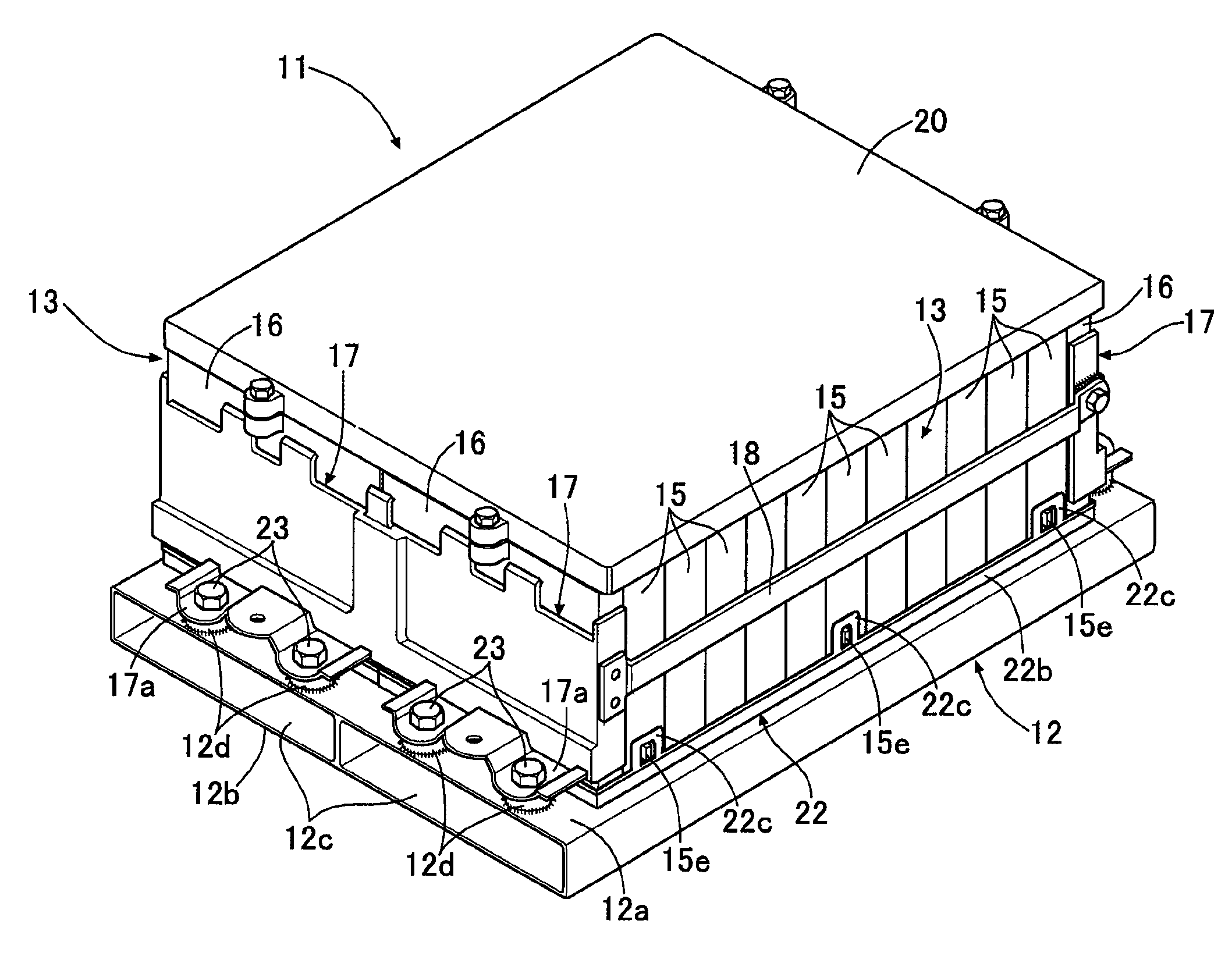
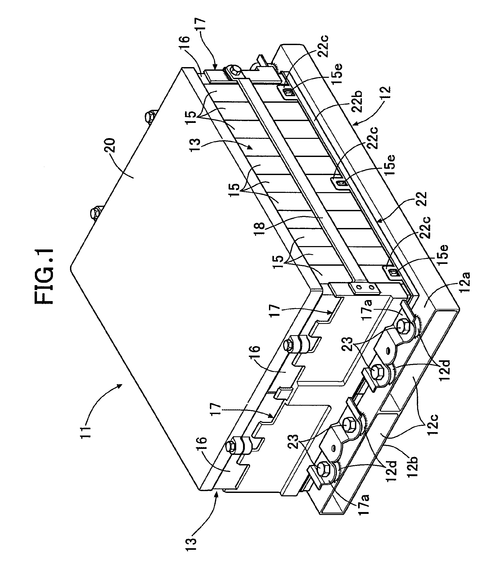
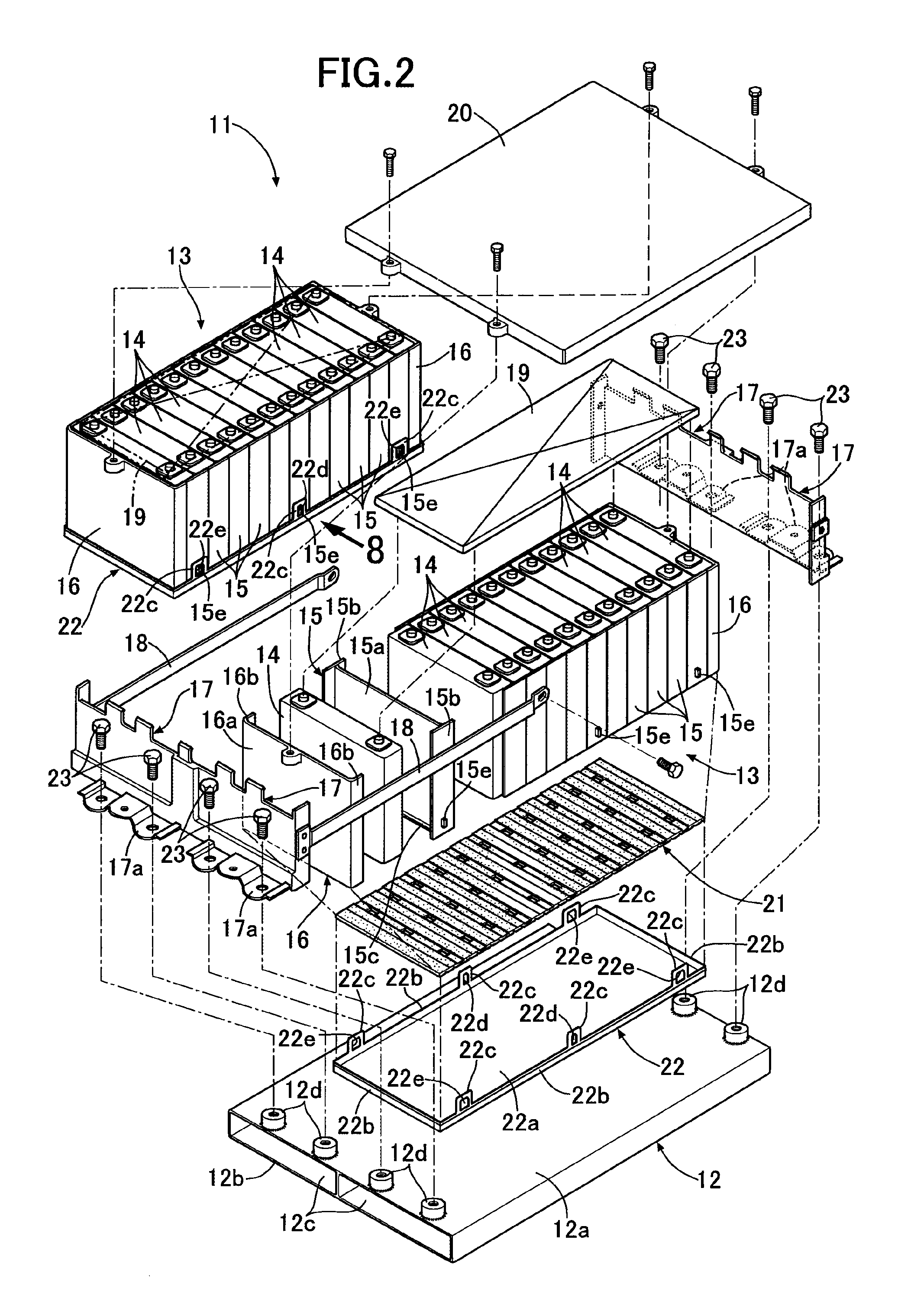
[0031]As shown in FIG. 1 and FIG. 2, a battery pack 11 mounted on an electric automobile is formed by supporting a plurality of battery modules 13 on a cooling plate 12; FIG. 1 and FIG. 2 show part of the cooling plate 12 and two battery modules 13 and 13. In the present embodiment, the two battery modules 13 and 13 are integrated, but the structures of the battery modules 13 are substantially identical.

[0032]The battery module 13 is formed by stacking a plurality (12 in the embodiment) of battery cells 14 each having a rectangular shape with synthetic resin intermediate holders 15 held therebetween and by stacking synthetic resin end holders 16 and 16 on outer sides of two battery cells 14 and 14 positioned at opposite ends in the stacking direction.

[0033]As shown in FIG. 3 to FIG. 6, the intermediate holder 15, whose horizontal cross section is formed into an H-shape, includes ...


PUM


Abstract

A battery cooling structure in which a heat transfer sheet that can be deformed by pressure is held between a cooling plate and a cooling surface of a battery module in which a plurality of battery cells are stacked, and heat of the battery module is transferred from the cooling surface to the cooling plate via the heat transfer sheet to thus carry out cooling, wherein the cooling plate is a hollow member in which a cooling medium passage is formed for a cooling medium to flow, and the heat transfer sheet is formed so as to have a larger thickness in a middle part than in an outer peripheral part.

Description

TECHNICAL FIELD[0001]The present invention relates to a battery cooling structure in which a heat transfer sheet that can be deformed by pressure is held between a cooling plate and a cooling surface of a battery module in which a plurality of battery cells are stacked, and heat of the battery module is transferred from the cooling surface to the cooling plate via the heat transfer sheet to thus carry out cooling.BACKGROUND ART[0002]When cooling is carried out by supporting a cooling surface of a battery module on a hollow cooling plate having a cooling medium flowing through its interior and transferring the heat of the battery module to the cooling plate via the cooling surface, since it is inevitable that a minute gap will occur between the cooling plate and the cooling surface of the battery module, which are both rigid, there is the problem that the performance in cooling the battery module is degraded due to inhibition of thermal conduction between the cooling surface and the ...

Claims


Application Information

Patent Timeline
IPC IPC(8): H01M10/6561H01M50/209
CPCH01M2220/20H01M10/5063H01M10/6561H01M10/6554Y02E60/10H01M50/209
Inventor KIMURA, ARIHISAKATAYAMA, GOICHI
Owner HONDA MOTOR CO LTD
Why Eureka
Try Eureka