
Rotary pruner

A technology of pruning machine and turning machine, which is applied to electric pruning saws, agricultural machinery and implements, cutting tools, etc., can solve the problems of increased work intensity, poor balance of the whole machine, heavy machine weight, etc., and achieves improved operating comfort. , the effect of good balance

Inactive Publication Date: 2015-11-11
广西融安颖丰科技开发有限公司
View PDF5 Cites 0 Cited by
  • Summary
  • Abstract
  • Description
  • Claims
  • Application Information

AI Technical Summary

Problems solved by technology

Since the pruning machine usually faces various shapes of working surfaces when pruning, the traditional pruning machine cannot be changed due to the use status, so that when pruning working surfaces with different angles such as side cutting or other different radian surfaces, the operator needs to Frequently adjust the posture of the human body or arms to rotate the machine to change the use state, which not only increases the work intensity, but also makes it difficult to meet the pruning needs in actual work
At the same time, this method usually causes poor balance of the whole machine. For example, when the side needs to be trimmed, the pruning machine needs to be used horizontally. Compared with the normal use of the pruning machine, the center of gravity of the whole machine relative to the handle will The position has changed greatly, and the center of gravity is located in a horizontal direction relative to the handle, so that the user will feel that the weight of the machine has become heavier, which will bring great discomfort to the arm and affect the comfort of the user during operation, especially On some pruning machines with larger battery pack capacity, this problem is more prominent

Method used


Image

  • Rotary pruner

Examples


Embodiment Construction

[0008] Embodiments provided by the present invention are described in further detail in conjunction with the accompanying drawings:

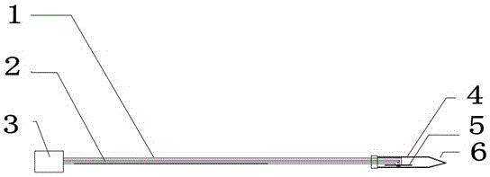
[0009] Such as figure 1 As shown, a rotary pruning machine includes a hollow long-distance rod 1, a rotating shaft 2 is arranged in the long-distance rod 1, a turning machine 3 is provided at one end of the long-distance rod 1, and a protective cover 4 is provided at the other end. The front end of the protective cover 4 is provided with a branch pad 6 , one end of the rotating shaft 2 is connected to the rotating machine 3 , and the other end is connected to the saw disc 5 .

[0010] The pruning machine of the present invention satisfies the working conditions of flat cutting, side cutting and other different arc surfaces through the rotation of the cutting assembly at different angles, and meets the needs of pruning different working planes, and at the same time changes the shearing plane of the cutting assembly through the rotating parts It ...


PUM


Abstract

The invention discloses a rotary pruner. The rotary pruner comprises a hollow long-distance rod. A rotary shaft is arranged in the long-distance rod. A rotary machine is arranged at one end of the long-distance rod, a protective cover is arranged at the other end of the long-distance rod, a branch pad is arranged at the front end of the protective cover, one end of the rotary shaft is connected with the rotary machine, and the other end of the rotary shaft is connected with a slitting disk. The rotary pruner meets the working conditions of truncation, side cutting and other different cambered surfaces through rotation of a cutting assembly at different angles, the requirements for pruning different working planes are met, the cutting plane of the cutting assembly is changed through a rotary part, the center-of-gravity position of the machine is barely affected, even though a battery pack with the large capacity is used, the balance of the whole machine is still good, and operating comfort is greatly improved.

Description

technical field [0001] The invention relates to the technical field of arboriculture, in particular to a rotary pruning machine. Background technique [0002] As a commonly used garden power tool, pruning machine can be used to trim or trim shrubs and hedges. As people's awareness and requirements for vegetation ecology and urban landscaping are increasing, their applications are becoming more and more extensive. Since the pruning machine usually faces various shapes of working surfaces when pruning, the traditional pruning machine cannot be changed due to the use status, so that when pruning working surfaces with different angles such as side cutting or other different radian surfaces, the operator needs to Frequently adjust the posture of the human body or arms to rotate the machine to change the use status, which not only increases the work intensity, but also makes it difficult to meet the pruning needs during actual work. At the same time, this method usually results i...

Claims


Application Information

Patent Timeline
Patent Type & Authority Applications(China)
IPC IPC(8): A01G3/08
CPCA01G3/088
Inventor 邱逸奎
Owner 广西融安颖丰科技开发有限公司
Learn More