Dust remover

A technology of dust collector and dust removal box, which is applied in the field of machinery, can solve problems such as explosion and fire extinguishing treatment, achieve high dust removal efficiency, and improve the effect of dust removal efficiency

Active Publication Date: 2015-11-11
陈美青
View PDF7 Cites 7 Cited by
  • Summary
  • Abstract
  • Description
  • Claims
  • Application Information

AI Technical Summary

Problems solved by technology

However, before the dust enters the dust collector, it is often accompanied by a large amount of sparks due to high-intensity processing, and the dust collector does not do any fire extinguishing treatment for the dust entering the dust removal box. If the dust contains a large amount of sparks and enters the dust collector There may be a risk of explosion behind the box, so the applicant still hopes to provide another dust collector to solve this problem

Method used


Image

  • Dust remover
  • Dust remover
  • Dust remover

Examples


Embodiment 1

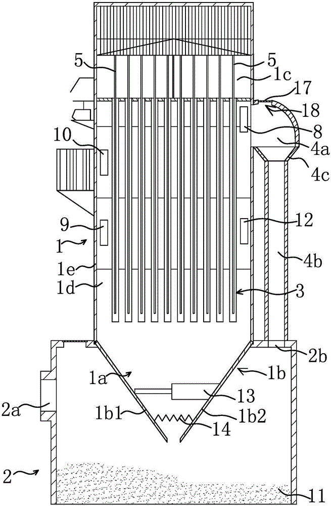
[0039] Such as figure 1 , figure 2 Shown, a kind of dust remover comprises dust removal box 1 and is positioned at dust storage box 2 below dust removal box 1, and dust removal box 1 is fixedly connected with dust storage box 2; Dust removal box 1 comprises dust removal chamber 1d and clean air chamber 1c, described A filter bag 3 is fixedly connected to the dust removal chamber 1d; after the air flows through the filter bag 3, the dust 11 is absorbed and then discharged again. The filter bag 3 can be a cloth bag or a filter cartridge, as long as it can achieve the effect of filtering the dust 11 . The ash storage box 2 is provided with a primary air inlet 2a and a primary air outlet 2b connected with the inner cavity of the ash storage box 2. The wind with dust 11 will first enter the ash storage box 2, and then pass through the ash storage box 2. To the dust removal box 1, the primary air outlet 2b of the ash storage box 2 is connected to the vertical branch pipe 4b, and ...

Embodiment 2

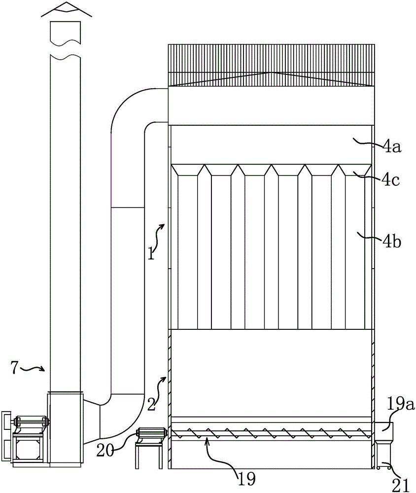
[0046] The structure and principle of this embodiment are basically the same as that of Embodiment 1, the difference is: the control element in this embodiment is a screw conveyor 19, and a motor for driving the screw conveyor 19 is arranged outside the dust removal box 1 20. Due to the poor working environment in the dust removal box 1, if the motor 20 is installed in it, it is easy to cause damage, so the motor 20 is installed on the bottom outside the dust removal box 1, between the first side plate 1b1 and the second side plate 1b2. A screw conveyor 19 is installed between the formed dust collection channel 1a and the motor 20, and the dust 11 at the bottom of the ash storage box 2 is transported to the outside of the dust removal box 1 for centralized recovery through the screw conveyor 19. For example, the ash outlet 19a of the spiral conveyor 19 can be positioned at the outside of the dust removal box 1, and the dust collection box 21 is connected below the ash outlet 19...

Embodiment 3

[0048] Such as Figure 5 As shown, the structure and principle of this embodiment are basically the same as that of Embodiment 1, the difference is that the fixing member includes a hinge 15, at least one ash discharge side plate 1b is hinged with the upper side plate 1e and the ash discharge side plate 1b is fixedly connected with the bottom of another ash discharge side plate 1b through a hinge 15 . When it is necessary to unload the ash, it is only necessary to remove the hinge 15, without the constraints of the hinge 15, at least one ash unloading side plate 1b is placed in a vertical state under the action of gravity, and its bottom edge is in contact with the adjacent A gap is formed between the ash discharge side plates 1b, and the ash collection channel 1a is in a connected state, and due to the blocking effect of the ash discharge side plates 1b, no ash phenomenon will occur during ash discharge.


PUM


Abstract

The invention provides a dust remover and belongs to the technical field of machinery. The dust remover solves the problem that an existing dust remover is easy to explode in the use process. The dust remover of an improved structure comprises a dedusting box and an ash storage box located below the dedusting box. The dedusting box is fixedly connected with the ash storage box. The dedusting box comprises a dedusitng cavity and an air purifying cavity. The dedusting cavity is internally and fixedly connected with a filtering bag. The dust remover is characterized in that the bottom of the dedusitng box is provided with an ash collection channel communicated with the ash storage box, the dedusting box is provided with an ash discharging mechanism capable of controlling the connected state or the cut-off state of the ash collection channel, the ash storage box is provided with a primary air inlet and a primary air outlet which are communicated with an inner cavity of the ash storage box, the dust remover further comprises a plurality of vertical supporting pipes vertically arranged, and the primary air outlet is communicated with the upper portion of the dedusting cavity of the dedusting box through the vertical supporting pipes. By means of the dust remover of the improved structure, explosion in the use process can be prevented, and safety performance is improved.

Description

technical field [0001] The invention belongs to the technical field of machinery, and relates to an air dust separation device, in particular to a dust collector. Background technique [0002] A dust collector is a device used to capture and separate dust particles suspended in air or gas. In the production and manufacturing of metallurgy, casting, cement building materials, machinery, light industry, and electric power, it is necessary to eliminate dust pollution, protect the environment, and improve working conditions. Therefore, the application of dust collectors is becoming more and more extensive. There are also many types of dust collectors. The most commonly used dust collectors are cyclone dust collectors, filter bag dust collectors, electric dust collectors, and wet dust collectors. [0003] For example, the applicant has previously declared a patent on dust collectors (application number: 200920314576.X; authorized announcement number: CN201572578U). The dust co...

Claims


Application Information

Patent Timeline
Patent Type & Authority Applications(China)
IPC IPC(8): B01D50/00
Inventor 陈美青
Owner 陈美青
Why Eureka
Try Eureka