
Centrifugal dehydrator for textile

A centrifugal dehydrator and textile technology, which is applied in the direction of liquid/gas/vapor removal by centrifugal force, can solve the problems of harshness, affecting the dehydration effect, and blockage of the dehydration holes of the dehydration basket, and achieves convenient use, good application prospects, and simple structure Effect

Inactive Publication Date: 2015-11-11
WUJIANG FUAILIANG TEXTILE
View PDF10 Cites 13 Cited by
  • Summary
  • Abstract
  • Description
  • Claims
  • Application Information

AI Technical Summary

Problems solved by technology

[0003] The purpose of the present invention is to overcome the existing centrifugal dehydrator. There are many impurities such as yarn and cotton wool on the textiles, which will easily cause the dehydration hole of the dehydration basket to be blocked and affect the dehydration effect. Moreover, when the motor and the dehydration basket of the centrifugal dehydrator rotate, Both make a lot of noise, very harsh problem

Method used


Image

  • Centrifugal dehydrator for textile

Examples


Embodiment Construction

[0015] The present invention will be further described below in conjunction with the accompanying drawings. The following examples are only used to illustrate the technical solution of the present invention more clearly, but not to limit the protection scope of the present invention.

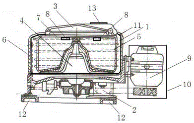
[0016] Such as figure 1 As shown, a centrifugal dehydrator for textiles includes a casing 1 made of cast iron. The bottom of the casing 1 is provided with a mounting base 2, and the bottom of the mounting base 2 is provided with a fixed foot bolt 12, which is firmly fixed. , to prevent shaking, the upper part of the housing 1 is provided with an end cover 3, one end of the end cover 3 is hinged on one side of the upper part of the housing 1 through a hinge 12, which is convenient to open and place the textiles to be dehydrated, and the center of the housing 1 A rotating mandrel 4 is provided, and a circle of dehydration basket 5 is arranged on the outside of the rotating mandrel 4. A drainage c...


PUM


Abstract

The invention discloses a centrifugal dehydrator for a textile. The centrifugal dehydrator comprises a shell. An installation base is arranged at the bottom of the shell. An end cover is arranged on the upper portion of the shell. A rotating spindle is arranged at the center in the shell. A circle of dehydration baskets are arranged on the outer side of the rotating spindle. A drainage channel is arranged between the dehydration baskets and the inner wall of the shell. An upper pressing plate is arranged above the dehydration baskets. Nylon filter nets are suspended below the upper pressing plate. A direct current motor is arranged on one side of the shell. The direct current motor is connected with the rotating spindle. The direct current motor is provided with a sound insulating cover. The inner wall of the shell is provided with a waterproof sound-insulating cotton layer. Due to the fact that the waterproof sound insulating cotton layer is arranged on the inner wall of the shell, and the sound insulating cover is arranged on the direct current motor, the sound insulating effect is good; due to the fact that the nylon filter nets are arranged in the dehydration baskets, impurities on the textile are filtered out and stored, and dehydration holes in the dehydration baskets and the drainage channel are prevented from being blocked; the centrifugal dehydrator is simple in structure, convenient to use and wide in application prospect.

Description

technical field [0001] The invention relates to a centrifugal dehydrator for textiles, belonging to the technical field of printing machinery. Background technique [0002] The centrifugal dehydrator uses mechanical centrifugal force to remove the moisture existing on the surface of the textile after wet treatment. Due to the centrifugal dehydration, the textile structure will not be deformed, and it has been widely used. In the current centrifugal dehydrator, since the dehydration is the textile in process, there are many impurities such as yarn and cotton wool on the textile, which will easily cause the dehydration hole of the dehydration basket to be blocked and affect the dehydration effect. Moreover, the motor of the centrifugal dehydrator, the dehydration basket When rotating, they all make a lot of noise, which is very harsh. Contents of the invention [0003] The purpose of the present invention is to overcome the existing centrifugal dehydrator. There are many im...

Claims


Application Information

Patent Timeline
IPC IPC(8): D06B15/10
Inventor 张福明
Owner WUJIANG FUAILIANG TEXTILE
Learn More