
Roof steel structure and construction method thereof

A steel structure and roof technology, applied to roofs, building components, building structures, etc., can solve the problems that string beams cannot withstand reverse loads, etc., and achieve the effect of light weight, good stability, and easy construction

Inactive Publication Date: 2015-11-11
中国华西企业股份有限公司
View PDF9 Cites 8 Cited by
  • Summary
  • Abstract
  • Description
  • Claims
  • Application Information

AI Technical Summary

Benefits of technology

This patented technology allows for efficient coordination across different parts of a building's framework while maintaining its integrity during heavy loads or impacts without adding extra material or making heavier structures than necessary. Additionally, this design improves the durability of the entire system by reducing damage from external forces such as rainwater and snowfall. Overall, these improvements improve energy efficiency and productivity within buildings.

Problems solved by technology

This patented describes a type of material called fiber reinforced plastic (FRP) that can be used for building materials such as buildings or bridges due its strengths against bending loads compared with traditional steel bars. However, it cannot support any significant force from reversely acting on them like weight bearing systems based upon tension cable technology.

Method used


Image

  • Roof steel structure and construction method thereof
  • Roof steel structure and construction method thereof
  • Roof steel structure and construction method thereof

Examples


Embodiment

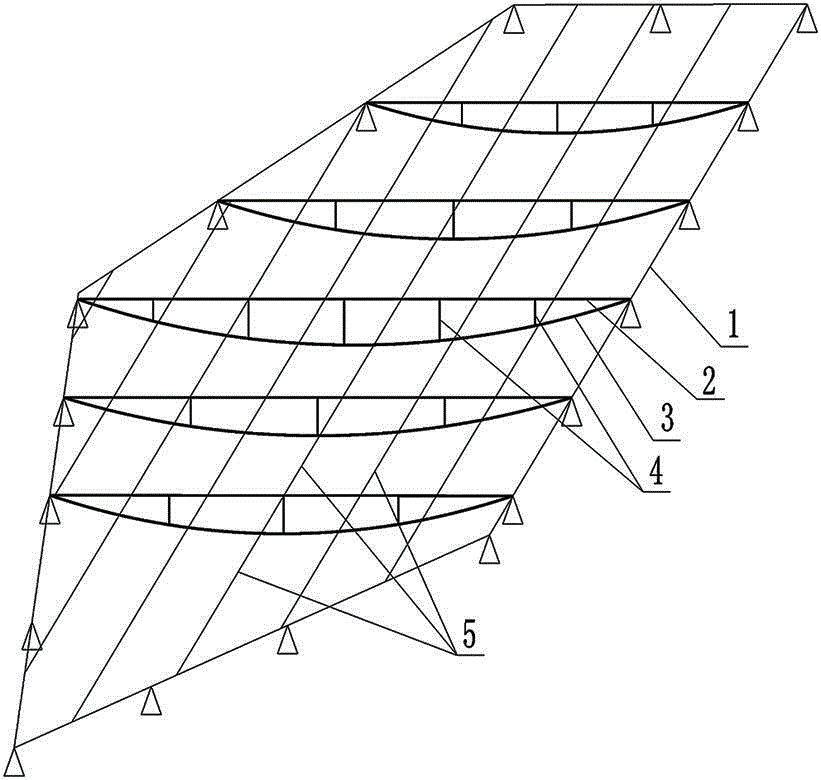
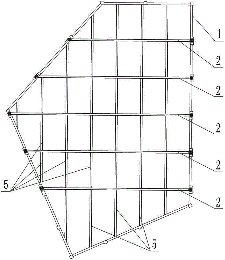
[0047] Such as figure 1 , figure 2 As shown, a roof steel structure, a roof steel structure, including a concrete frame 1 enclosing the outline of the roof, a plurality of horizontally arranged main beams and a plurality of longitudinally arranged secondary beams arranged in the concrete frame 1 , the concrete frame 1 is surrounded by a plurality of concrete beams extending in different directions. The concrete frame 1 is an arbitrary polygon, and each concrete beam is a side of the polygon. beam,

[0048] The main girder is a string beam composed of a rigid beam 2, a lower string 3 and a support rod 4, the two ends of the lower string 3 are fixedly connected to the two ends of the rigid beam 2, and the lower part of the rigid beam 2 is provided with a support rod 4 at intervals, One end of the support rod 4 is connected with the rigid beam 2, and the other end of the support rod 4 is connected with the lower string 3,

[0049] The concrete frame 1 is fixedly provided with...


PUM


Abstract

The invention discloses a roof steel structure. The roof steel structure comprises a concrete frame (1) encircled to form the roof contour, a plurality of main beams and a plurality of secondary beams, wherein the main beams and the secondary beams are arranged in the concrete frame (1). Each main beam is a beam string formed by a rigid beam (2), a lower chord rope (3) and a supporting rod (4). Each secondary beam is formed by a plurality of rigid secondary beam units (5). The two ends of the rigid secondary beam units located between two main beams are welded to the main beams on the two sides respectively. A roof steel structure construction process is further disclosed. The roof steel structure has the advantages that the matching application of the beam strings and the rigid beams is achieved, the beam strings and the rigid beams have complementary advantages, the roof steel structure has both the advantage of bearing vertical pressure through the beam strings and the advantage of bearing vertical and horizontal pressure and reverse pressure through the rigid secondary beams, so that the roof steel structure is good in stability; and compared with a rigid beam roof structure, the roof steel structure is light in self weight and convenient to construct.

Description


Claims


Application Information

Patent Timeline
Owner 中国华西企业股份有限公司
Learn More