Cam lock and rail vehicle with cam lock

A technology of cam lock and lock body, which is applied in building locks, buildings, building structures, etc., can solve the problems of loose lock structure, hidden safety hazards, and the inability of cam lock to meet the needs of use.

Inactive Publication Date: 2015-11-11
CRRC QINGDAO SIFANG CO LTD
View PDF4 Cites 4 Cited by
  • Summary
  • Abstract
  • Description
  • Claims
  • Application Information

AI Technical Summary

Problems solved by technology

[0003] The skirt of the equipment cabin is usually installed with a lock structure. With the increase of the operating speed of the rail vehicle, the requirements for the sealing of the skirt of the equipment cabin will be higher. Potential safety hazards, higher requirements are put forward for the bearing capacity and self-locking function of the rotary cam lock structure, and the existing rotary cam locks can no longer meet the needs of use

Method used


Image

  • Cam lock and rail vehicle with cam lock
  • Cam lock and rail vehicle with cam lock
  • Cam lock and rail vehicle with cam lock

Examples


Embodiment Construction

[0034] The core of the present invention is to provide a rotary cam lock, which has a large load-bearing capacity, can adapt to different working conditions and different load-bearing capacity apron installation requirements, and has a simple and reliable self-locking function and high safety. Another core of the present invention is to provide a rail vehicle with the above-mentioned rotary cam lock.

[0035] In order to enable those skilled in the art to better understand the solution of the present invention, the present invention will be further described in detail below in conjunction with the accompanying drawings and specific embodiments.

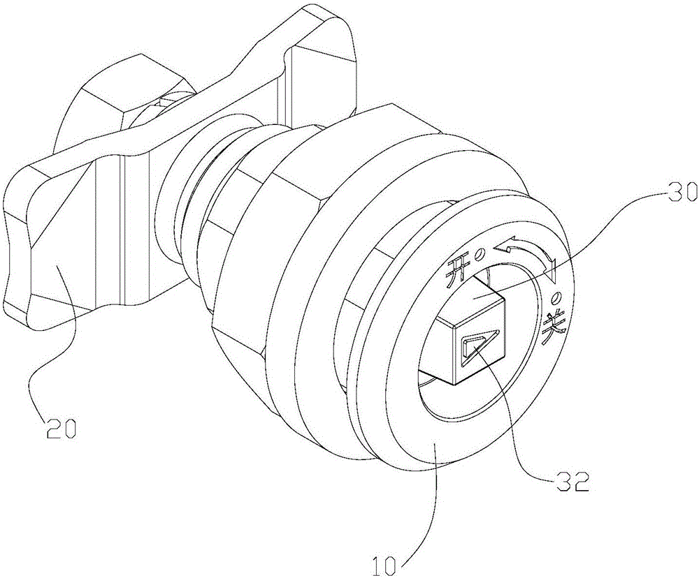
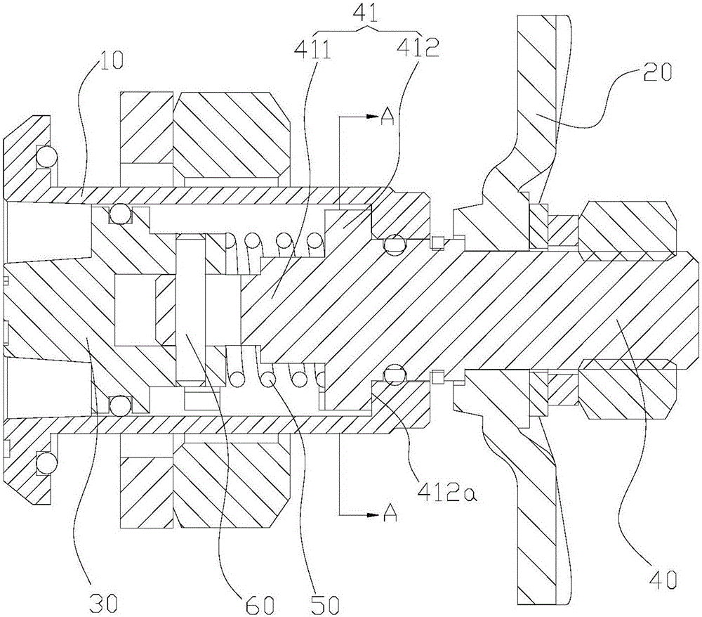
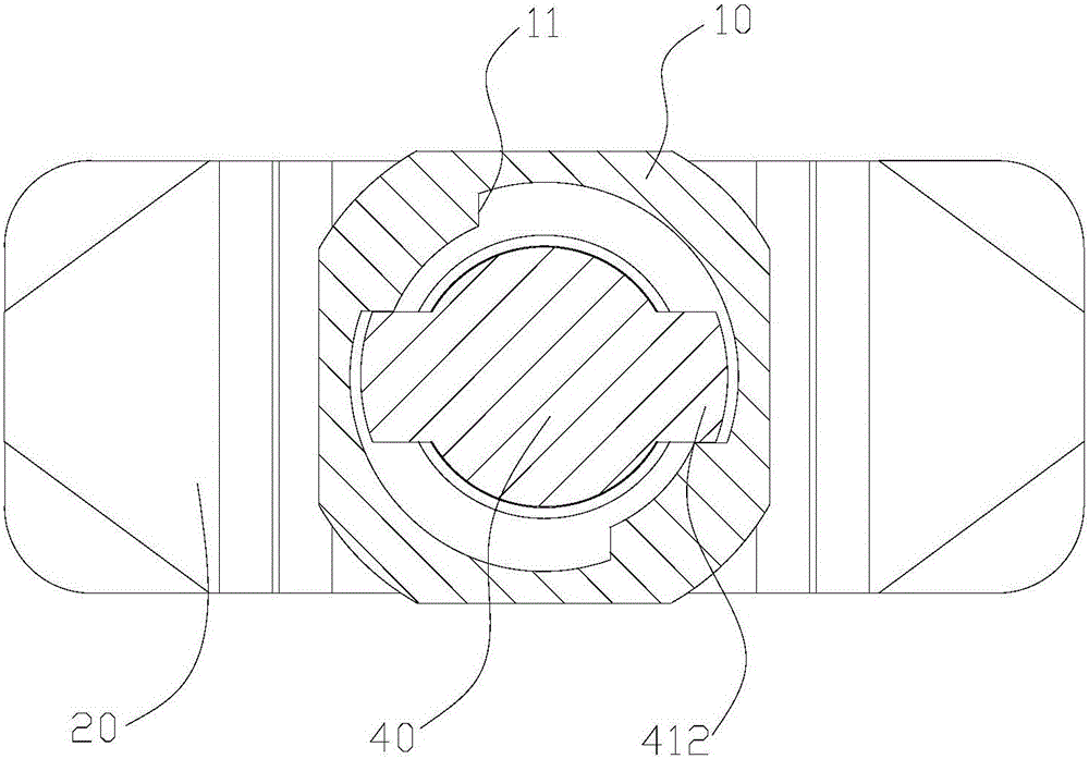
[0036] Please refer to Figure 1-2 , figure 1 It is an axonometric view of the rotary cam lock in the specific embodiment; figure 2 for figure 1 Cutaway view of the turntable lock shown in .

[0037] In this embodiment, the rotary cam lock includes a lock body 10, a lock tongue 20 and a lock cylinder.

[0038] How to assemble th...


PUM


Abstract

The invention discloses a cam lock. The cam lock comprises a lock body, a bolt and a lock cylinder. The lock cylinder comprises an outer lock cylinder body and an inner lock cylinder body. The head of the inner lock cylinder body is located in a through hole of the lock body and comprises a lap joint face in lap joint with the inner end face of the lock body. The tail of the inner lock cylinder body extends out of the lock body. The bolt is fixedly arranged at the tail of the inner lock cylinder body in a sleeving mode. The outer lock cylinder body is arranged in the through hole of the lock body, can slide towards the inner lock cylinder body and can be matched with the inner lock cylinder body so as to rotate jointly. A reset spring is arranged between the outer lock cylinder body and the inner lock cylinder body. The cam lock is large in bearing capacity and can meet the requirements of installing skirting boards with different bearing capacities under different working conditions; in addition, the self-locking function is simple and reliable, and safety is high. The invention further discloses a rail vehicle with the cam lock.

Description

technical field [0001] The invention relates to the technical field of engineering machinery, in particular to a rotary cam lock. The invention also relates to a rail vehicle having a rotary cam lock as described above. Background technique [0002] For existing rail vehicles, such as urban light rail, passenger trains, EMUs, etc., in order to save space in the vehicle and facilitate the installation and configuration of pipelines and lines for equipment devices, the relevant vehicle equipment is usually arranged under the chassis of the vehicle body to form a Equipment compartment under the vehicle. [0003] The skirt of the equipment cabin is usually installed with a lock structure. With the increase of the operating speed of the rail vehicle, the requirements for the sealing of the skirt of the equipment cabin will be higher. In order to prevent the lock structure from loosening due to vibration when the rail vehicle is running at high speed, causing Potential safety ha...

Claims


Application Information

Patent Timeline
Patent Type & Authority Applications(China)
IPC IPC(8): E05B63/00E05B15/00
Inventor 王兆华梁建英李明珍王维峰田爱琴鄢桂珍陶桂东丁叁叁
Owner CRRC QINGDAO SIFANG CO LTD
Why Eureka
Try Eureka