
Exhaust gas turbocharger with rotor and its radial bearing bushing

A radial bearing and exhaust gas turbine technology, applied in the direction of rotating bearings, bearings, bearing components, etc., can solve limited problems, achieve the effect of preventing frictional movement, improving installation, and improving quiet operation

Active Publication Date: 2018-02-23
BMTS TECH SHANGHAI CO LTD
View PDF7 Cites 0 Cited by
  • Summary
  • Abstract
  • Description
  • Claims
  • Application Information

AI Technical Summary

Problems solved by technology

In order to reduce this risk, it is ideal to place the two radial bearing bushes as far apart axially as possible with the installation of the two bushes, however, this is only possible to a limited extent due to the structural peripheral conditions of the bearing housing

Method used


Image

  • Exhaust gas turbocharger with rotor and its radial bearing bushing
  • Exhaust gas turbocharger with rotor and its radial bearing bushing
  • Exhaust gas turbocharger with rotor and its radial bearing bushing

Examples


Embodiment Construction

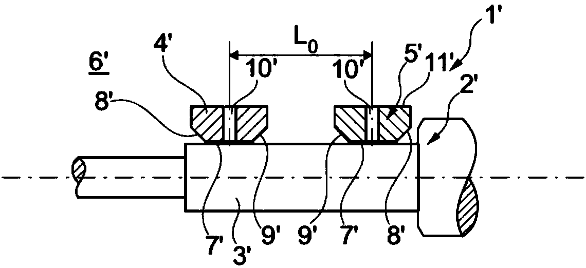
[0016] according to figure 1 , an exhaust gas turbocharger 1' according to the prior art comprises a rotor 2' whose shaft 3' is mounted in a bearing housing 6' via two radial bearing bushes 4' and 5'. The two radial bearing bushes 4' and 5' respectively have two bevels 8' and 9' on their inner surface 7' facing the shaft 3', wherein the bevels 8' and 9' are formed to have the same dimensions. This produces a center-to-center axial spacing L of the two inner surfaces 7' 0 .

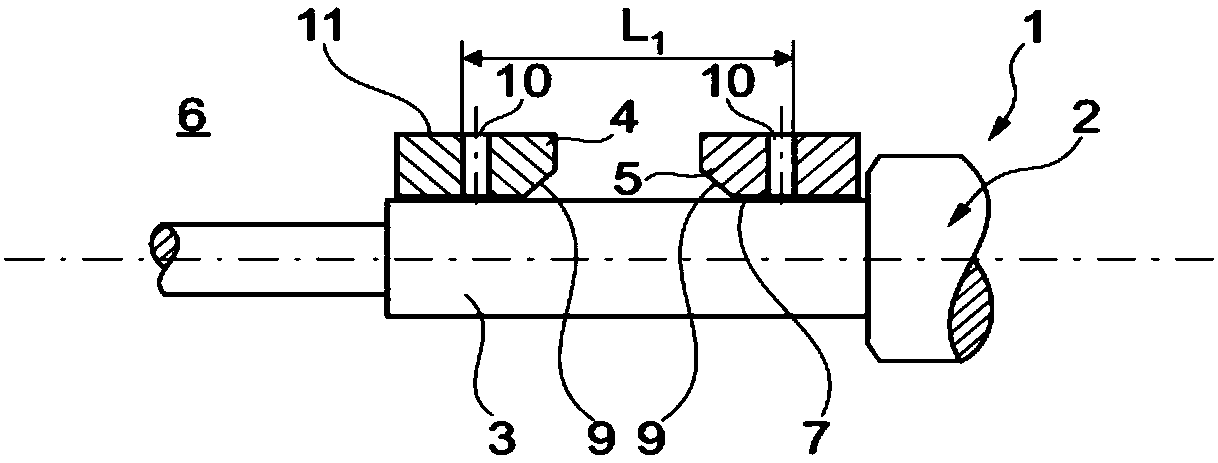
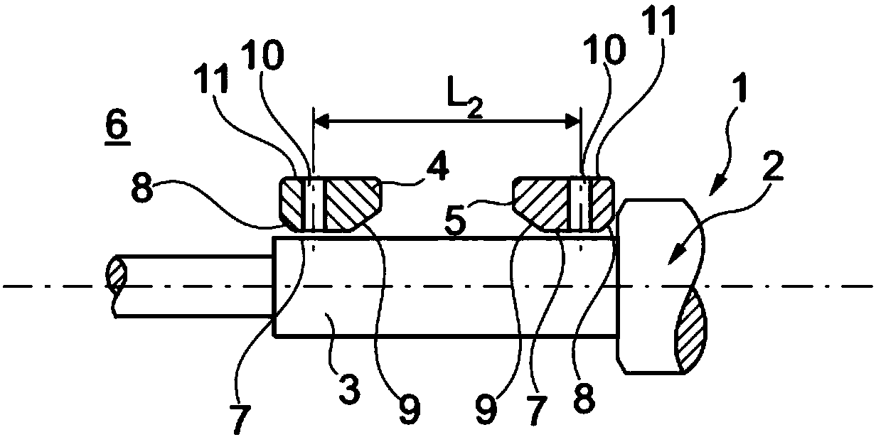
[0017] according to Figure 2 to Figure 4 , the exhaust gas turbocharger 1 according to the invention similarly comprises a rotor 2 whose shaft 3 is mounted in a bearing housing 6 via two radial bearing bushes 4 , 5 . and figure 1 In this case, by contrast, the reference numerals are written without an apostrophe. see figure 2 It is presently evident that each of the two radial bearing bushes 4 , 5 according to the invention has only a single bevel 9 on its inner surface 7 facing the shaft 3 , which...


PUM


Abstract

The invention relates to an exhaust gas turbocharger (1) comprising a rotor (2), the shaft (3) of which is mounted via two radial bearing bushes (4, 5) on the in the bearing housing (6). In this case, the essence of the invention is that each radial bearing bush (4, 5) comprises a single bevel (9) on the inner surface (7) facing said shaft (3), said radial in the mounted state The radial bearing bushes face each other; or each radial bearing bush (4, 5) comprises two inclined surfaces (8, 9) on the inner surface (7) facing the shaft (3), wherein the mounted state faces each other The paired slopes (9) are larger than the slopes (8) facing away from each other in the installed state.

Description

technical field [0001] The invention relates to an exhaust gas turbocharger comprising a rotor, the shaft of which is mounted in a bearing housing via two radial bearing bushes. The invention also relates to a radial bearing bush for such an exhaust gas turbocharger. Background technique [0002] During operation, spent turbochargers are exposed to rotational speeds well in excess of 100,000 rpm. Typically, hydrodynamic bearings are used as radial bearings, comprising two floating bearing bushes or a so-called single bushing installation. In this case, an undesired characteristic of the hydrodynamic installation is that an unstable rotational movement of the shaft as well as a rotational movement of the rotor may occur through the flow effect of the oil film formed between the bearing bushing and the shaft of the rotor, whereby, at the most In poor cases, the rotor performs a stirring or oscillating motion. In order to reduce this risk, it is desirable to arrange the two ...

Claims


Application Information

Patent Timeline
Patent Type & Authority Patents(China)
IPC IPC(8): F02C7/06F01D25/16F16C33/04
CPCF01D25/16F05D2220/40F05D2250/293F16C17/02F16C17/18F16C17/26F16C35/02F16C2360/24F01D25/162F16C17/022F16C33/04F16C33/046F16C35/10F16C2240/26
Inventor 吕迪格·克莱因施密特乌尔里希·肖亚历山大·博伊尔勒托马斯·施特里德尔迈尔约而格·埃克特克里斯托弗·布切尔
Owner BMTS TECH SHANGHAI CO LTD
Learn More