
Infrared LED lamp bead for security and protection and infrared lamp panel for security and protection

A technology of LED lamp beads and infrared lamp boards, which is applied to the parts of lighting devices, cooling/heating devices of lighting devices, lighting devices, etc. Poor and other problems

Inactive Publication Date: 2015-11-11
王肆军
View PDF5 Cites 0 Cited by
  • Summary
  • Abstract
  • Description
  • Claims
  • Application Information

AI Technical Summary

Problems solved by technology

The defect of this prior art is obvious: First, since the input voltage of the infrared device is 12V, and the operating voltage of a single infrared LED chip is 1.5-2.2V, the total voltage of the two together is only 3- 4.4V, so it is necessary to add an additional set of step-down and step-up current circuits, which makes the entire circuit board very complicated, which not only increases the cost, but also makes the heat dissipation effect worse; secondly, there is only one LED chip in a single lamp bead in the prior art, As a result, the light energy is strong in the middle and the edge is weak. The optical lens must be frosted or textured to make the output light energy uniform, and this will obviously consume the output energy of the light; again, the drive circuit in the prior art uses a switch type The cost of the constant current circuit is relatively high; finally, due to the small number of LED chips used in the existing technology, in order to meet the needs of infrared shooting, the power must be increased, which will cause the heat of the LED to increase sharply

Method used


Image

  • Infrared LED lamp bead for security and protection and infrared lamp panel for security and protection
  • Infrared LED lamp bead for security and protection and infrared lamp panel for security and protection
  • Infrared LED lamp bead for security and protection and infrared lamp panel for security and protection

Examples


Embodiment Construction

[0027] In order to make the technical problems, technical solutions and advantages to be solved by the present invention clearer, the present invention will be further described in detail below in conjunction with the accompanying drawings and embodiments. It should be understood that the specific embodiments described here are only used to explain the present invention, not to limit the present invention.

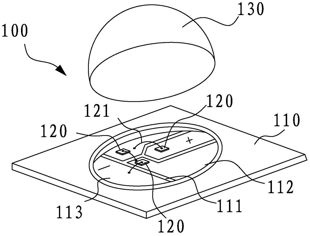
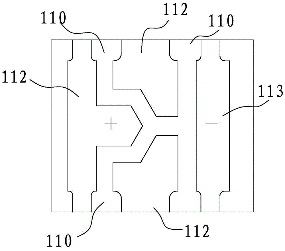
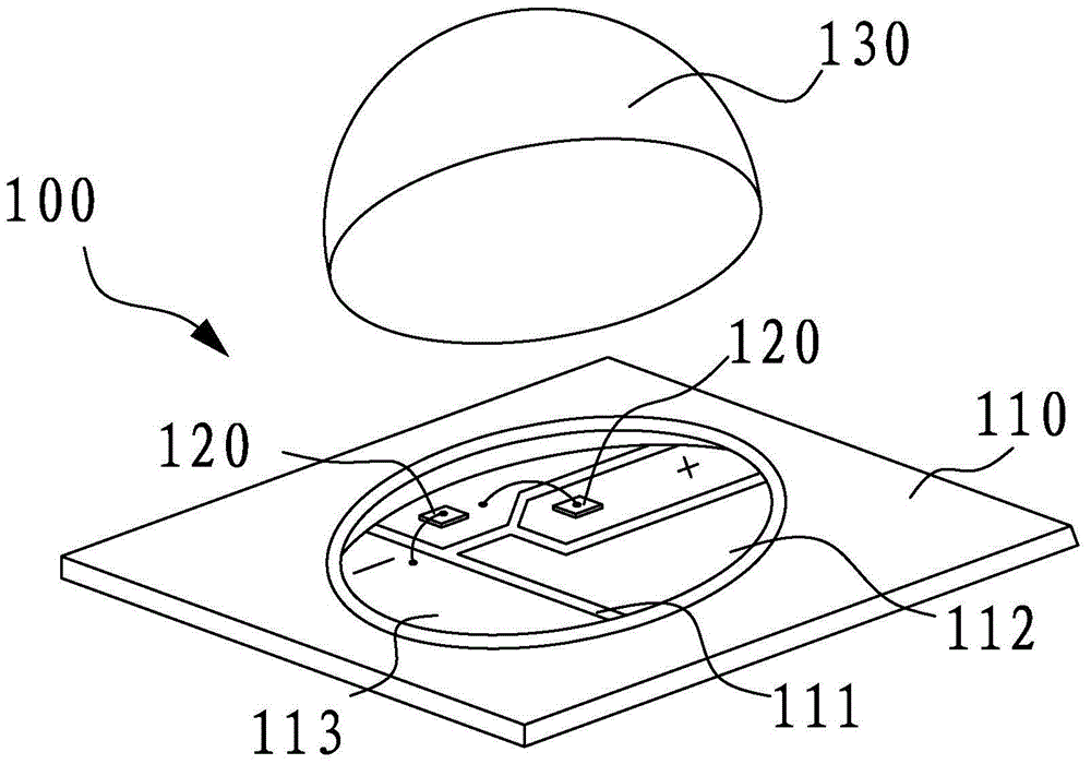
[0028] All the drawings only disclose the part closely related to the present invention, but not the whole structure. Such as figure 1 , 2 Shown is the first embodiment of the infrared LED light bead provided by the present invention, which is applied in the security field. The infrared LED lamp bead 100 includes a lamp bead bracket 110, and 2 to 6 infrared LED chips 120 are installed on the lamp bead bracket 110, and the infrared LED chips 120 are all connected through a series circuit, A lens 130 is also covered thereon. In this embodiment, the light emitting angle o...


PUM

PropertyMeasurementUnit
Wavelengthaaaaaaaaaa
Beam angleaaaaaaaaaa

Abstract

The invention relates to the field of infrared security and protection, in particular to an infrared LED lamp bead for security and protection and an infrared lamp panel for security and protection. The infrared LED lamp bead comprises a lamp bead support. The lamp bead support is provided with two to six infrared LED chips, wherein all the infrared LED chips are connected through a series circuit. The infrared lamp panel comprises a substrate and at least one infrared LED lamp bead. Each infrared LED lamp bead comprises one lamp bead support. The lamp bead supports are arranged on the substrate. Each lamp bead support is provided with at least two infrared LED chips which are connected through the series circuit. The sum of the infrared LED chips connected in series on the substrate is smaller than or equal to six. The loss of light energy is reduced, and distribution of luminous intensity is even. Furthermore, due to the fact that the number of the chips is increased, the power of each single chip can be lowered relatively, and the overall heat dissipation effect is better than that of the prior art.

Description

technical field [0001] The invention relates to the field of infrared and security, in particular to an infrared LED lamp bead for security and an infrared lamp board for security. Background technique [0002] With the continuous development of technology and the continuous improvement of living standards, security systems have become an indispensable part of people's daily life, such as closed-circuit monitoring systems, anti-theft alarm systems, community card systems, infrared perimeter alarm systems, etc. are all security systems . [0003] According to different working principles, security systems can be divided into infrared, microwave, laser, sound detection and other categories. Among them, the infrared security system is relatively mature in technology, and occupies a relatively important position in the entire security field. In the infrared security system, the infrared camera is one of the most common devices. [0004] As we all know, infrared cameras are us...

Claims


Application Information

Patent Timeline
IPC IPC(8): F21V19/00F21V23/06F21V29/503F21Y101/02
CPCF21V19/001F21V23/06
Inventor 王肆军
Owner 王肆军
Learn More