Pulse tube refrigerator and flow guide structure thereof
A pulse tube refrigerator and pulse tube technology, applied in refrigerators, gas cycle refrigerators, refrigeration components, etc., can solve problems such as poor diversion effect, and achieve low resistance loss, uniform airflow, and improved cooling capacity. Effect
- Summary
- Abstract
- Description
- Claims
- Application Information
AI Technical Summary
Problems solved by technology
Method used
Image

Examples
Embodiment 1
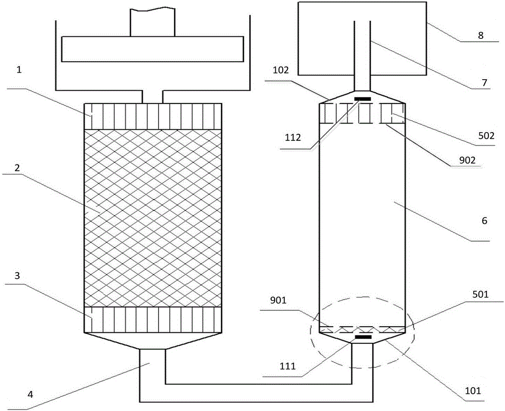
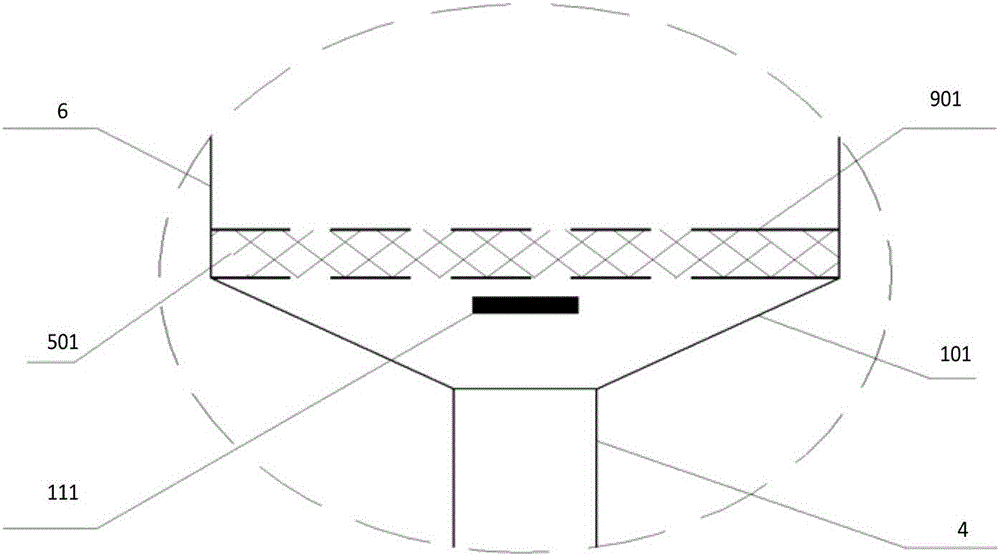
[0032] Such as Figure 2-5 As shown, in addition to the existing cold-end connecting pipe 4, pulse tube 6, and inertial tube 7, the flow guide structure of the pulse tube refrigerator of the present invention also includes a first flow guide layer 501 and a second flow guide layer located in the pulse tube 6. Two diversion layers 502 . Wherein preferably, the first flow-guiding layer 501 and the second flow-guiding layer 502 are uniform porous materials; the first flow-guiding layer 501 and the second flow-guiding layer 502 can be 40 mesh silk The mesh material may have a thickness of about 3mm. In order to achieve a good cooling effect, the thickness of the second flow-guiding layer 502 is generally greater than that of the first flow-guiding layer 501 . Because the wire mesh of the flow-guiding layer is relatively thin and soft, in order to prevent the wire mesh from being deformed under the action of the air flow and affecting the flow-guiding effect, preferably, the flow-...
Embodiment 2
[0037] Such as Figure 6-7 As shown, in addition to the existing cold-end connecting pipe 4, pulse tube 6, and inertial tube 7, the flow guide structure of the pulse tube refrigerator of the present invention also includes a first flow guide layer 501 and a second flow guide layer located in the pulse tube 6. Two diversion layers 502 . Preferably, the first flow guide layer 501 and the second flow guide layer 502 are uniform porous materials, and the thickness of the second flow guide layer 502 is generally greater than that of the first flow guide layer 501 . The first flow guide layer 501 and the second flow guide layer 502 can be fiber mat materials with less resistance, the thickness can be increased to about 5 mm, and after the fiber mats are sintered at high temperature, the fiber webs have been bonded to each other Together, they have greater rigidity, so no brackets are needed to fix them, making the structure simpler.
[0038] The flow guide structure also includes:...
Embodiment 3
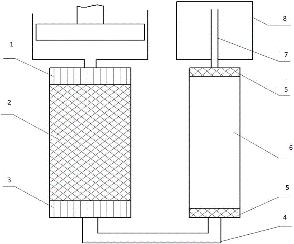
[0040] The present invention also provides a pulse tube refrigerator, including a main radiator 1, a regenerator 2, a cold-end heat exchanger 3, and a gas store 8, and also includes the guide of the pulse tube refrigerator described in Embodiment 1 or 2 above. stream structure.
[0041] By adopting the diversion structure of the present invention, the resistance loss is small during the diversion process, the diversion effect is greatly improved, the air flow in the pulse tube flows evenly, and the cooling capacity of the refrigerator is greatly improved.
PUM
 Abstract
Description
Claims
Application Information
 - Generate Ideas
- Intellectual Property
- Life Sciences
- Materials
- Tech Scout
- Unparalleled Data Quality
- Higher Quality Content
- 60% Fewer Hallucinations
Browse by: Latest US Patents, China's latest patents, Technical Efficacy Thesaurus, Application Domain, Technology Topic, Popular Technical Reports.
© 2025 PatSnap. All rights reserved.Legal|Privacy policy|Modern Slavery Act Transparency Statement|Sitemap|About US| Contact US: help@patsnap.com