Blade tip coupled cooling experiment system for turbine blades of gas turbine

A technology of turbine blades and experimental systems, which is applied in gas turbine engine testing, jet engine testing, etc., can solve the problems of single external film cooling research content and affect the film flow structure, so as to save research costs and enhance flow mixing. Mixed, Experimental Study of Simple Effects

Active Publication Date: 2018-10-02
XI AN JIAOTONG UNIV
View PDF5 Cites 12 Cited by
  • Summary
  • Abstract
  • Description
  • Claims
  • Application Information

AI Technical Summary

Problems solved by technology

In the current experimental research on blade top cooling, the research on internal and external cooling is carried out independently, and the research content of external film cooling is relatively single. However, from the macroscopic point of view of blade top cooling, internal and external cooling interact and work together , the enhanced heat transfer structure of the inner surface will definitely affect the flow structure of the outer air film, and the setting of the air film holes also determines the flow and heat transfer distribution of the inner surface. The independent research results of the two may have a greater difference with the actual situation deviates, so a cooling experiment system for coupling inside and outside the blade tip is needed

Method used


Image

  • Blade tip coupled cooling experiment system for turbine blades of gas turbine
  • Blade tip coupled cooling experiment system for turbine blades of gas turbine
  • Blade tip coupled cooling experiment system for turbine blades of gas turbine

Examples


Embodiment Construction

[0042] The present invention will be described in further detail below in conjunction with the accompanying drawings and specific embodiments.

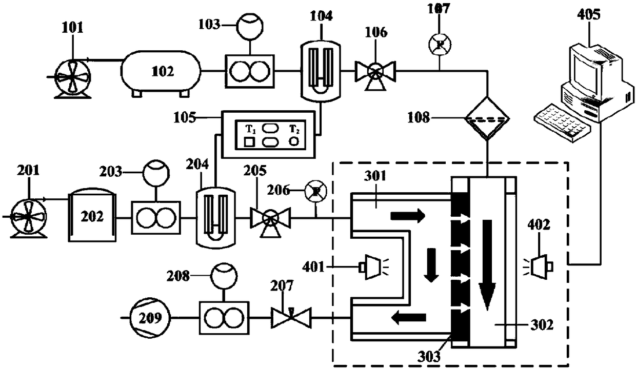
[0043] see figure 1 The present invention provides a blade tip coupling cooling experiment system for a turbine blade of a gas turbine, which includes a high-temperature mainstream passage, a U-shaped cooling passage, an experimental test section, and a data acquisition and analysis system.

[0044] refer to figure 1 , the high-temperature mainstream path includes a mainstream gas pump 101, a mainstream gas stabilizing tank 102, a mainstream gas flow meter 103, a mainstream gas heater 104, a temperature control box 105, a mainstream three-way solenoid valve 106, a mainstream gas pressure gauge 107 and a mainstream gas rectifying filter Net 108. The air at room temperature enters the high-temperature main channel through the main air pump 101, and after being pressure-compensated by the main flow tank 102, it flows stably into the ma...


PUM


Abstract

The invention discloses a blade tip coupled cooling experiment system for turbine blades of a gas turbine. The blade tip coupled cooling experiment system comprises a high temperature main flow channel, a U-shaped cooling channel, an experimental test section and a data acquisition and analysis system, wherein the high temperature main flow channel comprises a temperature control box, and a main flow gas pump, a main flow gas flow stabilization tank, a main flow gas heater and a main flow three-way electromagnetic valve which are sequentially connected; the U-shaped cooling channel comprises acold flow outlet vacuum pump, and a cold flow inlet gas pump, a cooling gas flow stabilization tank, a cooling gas heater and a cold flow inlet three-way electromagnetic valve which are sequentiallyconnected; the experimental test section comprises a U-shaped cooling channel, a high-temperature main flow channel and a blade tip plate with a through hole in the center, and an embedded plate is embedded in the through hole; the data acquisition and analysis system comprises a cooling channel infrared thermal imager, a main flow channel infrared thermal imager, a CCD camera, and a data acquisition and analysis computer connected with the cooling channel infrared thermal imager, the main flow channel infrared thermal imager and the CCD camera; and an outlet of the main flow three-way electromagnetic valve is communicated to an inlet of the high temperature main flow channel, and an outlet of the cold flow inlet three-way electromagnetic valve is communicated to an inlet of the U-shaped cooling channel.

Description

technical field [0001] The invention belongs to the technical field of cooling of turbine blades of gas turbines, in particular to a blade top coupling cooling experiment system of turbine blades of gas turbines. Background technique [0002] Gas turbine is a high-end industrial equipment in the field of energy and power. It is technically difficult, has a large number of components, requires high technology, covers a wide range of fields, and has huge global demand. It is a concentrated expression of a country's industrial strength, technological level, and comprehensive national strength. As the gas temperature at the turbine inlet continues to rise, the blades are subjected to high heat loads in actual operation, even far exceeding the allowable temperature of the blade material. Therefore, the development of efficient cooling technology for blades has become an important part of the development of gas turbine topic. [0003] The top of the blade is a relatively special ...

Claims


Application Information

Patent Timeline
Patent Type & Authority Applications(China)
IPC IPC(8): G01M15/14
CPCG01M15/14
Inventor 张荻景祺谢永慧
Owner XI AN JIAOTONG UNIV
Why Eureka
Try Eureka