Single-tower dual-cycle wet flue gas desulfurization tower and tube groove type liquid collection device

A tube-trough, liquid-collecting technology, applied in the field of flue gas desulfurization, can solve the problems of uneven distribution of flue gas flow rate, insufficient gas-liquid contact, and reduced mass transfer capacity, and achieves good gas-liquid contact effect, avoids short circuits, The effect of reducing drag loss

Active Publication Date: 2016-03-23
SHANDONG UNIV
View PDF14 Cites 13 Cited by
  • Summary
  • Abstract
  • Description
  • Claims
  • Application Information

AI Technical Summary

Problems solved by technology

The above-mentioned patent documents represent relatively advanced research results on liquid collection devices in this technical field. However, the above-mentioned liquid collection devices have the following disadvantages: when the flue gas flows through these liquid collection devices from the lower circulation to the upper circulation , will often cause a large resistance loss, and the distribution of the flue gas flow rate in the upper circulation loop will also become uneven, resulting in insufficient gas-liquid contact in the tower and a decrease in mass transfer capacity, which will eventually affect the desulfurization efficiency.

Method used


Image

  • Single-tower dual-cycle wet flue gas desulfurization tower and tube groove type liquid collection device
  • Single-tower dual-cycle wet flue gas desulfurization tower and tube groove type liquid collection device
  • Single-tower dual-cycle wet flue gas desulfurization tower and tube groove type liquid collection device

Examples


Embodiment 1

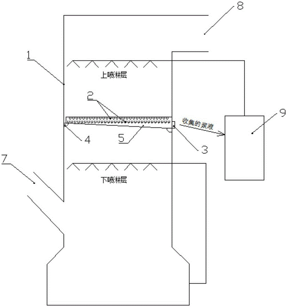
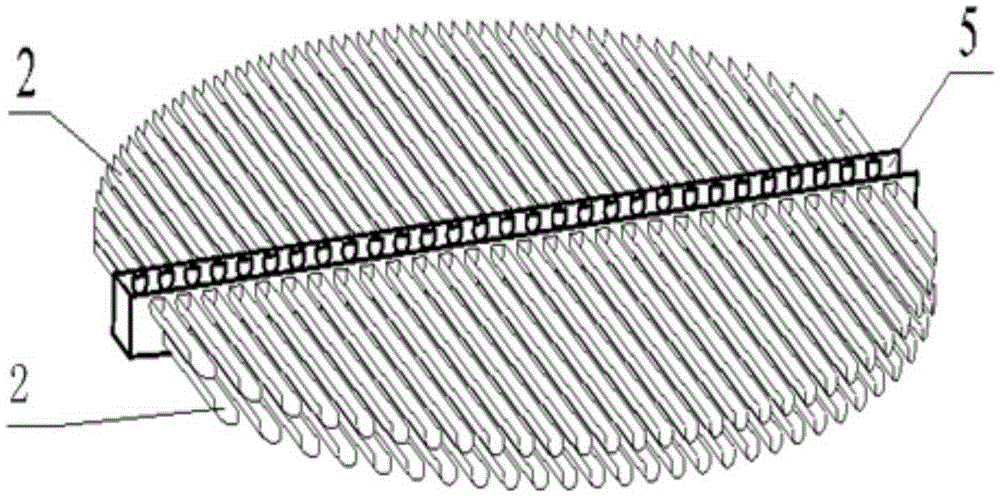
[0030] Such as image 3 shown. A pipe-groove type liquid collection device, comprising several liquid-collecting pipe grooves 2, the liquid-collecting pipe groove 2 is a long semi-circular pipe groove with an open top, the liquid-collecting pipe groove 2 is provided with two layers in the longitudinal direction, and the two-layer liquid collecting pipe The grooves 2 are arranged in a staggered manner, and the liquid collecting pipe grooves on the same layer are evenly arranged. The distance between two adjacent liquid collecting pipe grooves on the same layer is equal to the width of the opening of the liquid collecting pipe grooves, so as to realize the collection of the upper spray layer slurry At the same time, the system resistance is reduced, and the gap between the collecting pipe grooves 2 forms a flue gas channel.

[0031] In order to make the flue gas pass smoothly through the liquid collecting pipe grooves arranged in the groove grid type and reduce the resistance l...

Embodiment 2

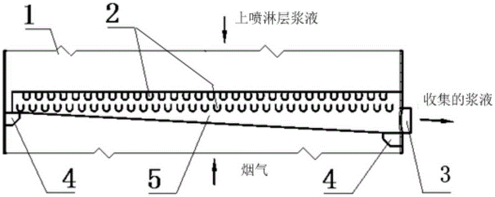
[0041] The features of this embodiment that are the same as those of Embodiment 1 will not be described in detail. The features of this embodiment that are different from Embodiment 1 are: Figure 4 As shown, the liquid collecting pipe groove 2 is distributed symmetrically on both sides of a support rod 6 , and the diversion groove 5 surrounds the end of the liquid collecting pipe groove 2 away from the supporting rod 6 . The diversion groove 5 is located at the outer end of the collecting pipe groove 2 and communicates with all the collecting pipe grooves 2 at the same time. One end of the collecting pipe groove 2 communicating with the diversion groove 5 is lower than the other end, so that the collecting pipe groove 2 form a "Λ" shape arrangement as a whole.

[0042] In order to avoid affecting the flue gas flow while ensuring that the slurry is easy to flow, the bottom surface of the diversion groove 5 includes an inner bottom surface in contact with the slurry and an oute...

Embodiment 3

[0045] The features of this embodiment that are the same as those of Embodiment 1 will not be described in detail. The features of this embodiment that are different from Embodiment 1 are: Figure 5 As shown, the overall collection pipe groove 2 is inclined in the same direction, and the diversion groove 5 is located at the lower end of the liquid collection pipe groove 2 and communicates with all the liquid collection pipe grooves 2 at the same time.

[0046] In this embodiment, the diversion groove 5 is located at the edge of the entire pipe groove liquid collection device. In order to avoid affecting the flow of flue gas and ensure that the slurry is easy to flow, the bottom surface of the diversion groove 5 includes the bottom surface of the inner layer that is in contact with the slurry As for the bottom surface of the outer layer in contact with the flue gas, the bottom surface of the inner layer is an inclined surface, and the bottom surface of the outer layer is a horiz...


PUM


Abstract

The invention provides a single-tower dual-cycle wet flue gas desulfurization tower and a tube groove type liquid collection device, and belongs to the technical field of flue gas desulfurization. The desulfurization tower comprises a tower body, the bottom of the tower body is provided with a flue gas inlet, the top of the tower body is provided with a flue gas outlet, an upper spray layer and a lower spray layer are arranged on the portion, between the flue gas inlet and the flue gas outlet, inside the tower body, and the tube groove type liquid collection device is installed between the upper spray layer and the lower spray layer and separates slurry of the upper spray layer from slurry of the lower spray layer; the tube groove type liquid collection device comprises multiple liquid collection tube grooves which are formed for multiple layers in the longitudinal direction, the two adjacent layers of the liquid collection tube grooves are arranged in a staggered mode, the liquid collection tube grooves are arranged in an inclined mode, and the lower ends of the liquid collection tube grooves are communicated with a diversion groove. According to the single-tower dual-cycle wet flue gas desulfurization tower and the tube groove type liquid collection device, the flow field is uniformly distributed, the resistance loss of the structural design is small, and the contact effect between the gas and liquid is good. Therefore, the slurry of the upper spray layer can be collected, the system resistance can be reduced, and the desulphurization efficiency is improved.

Description

technical field [0001] The invention relates to the technical field of flue gas desulfurization, in particular to a single-tower double-circulation wet flue gas desulfurization tower and a pipe-trough type liquid collection device. Background technique [0002] At present, the air pollution caused by coal-fired power plants has been paid more and more attention, and my country's emission standards for air pollutants from coal-fired power plants are becoming more and more stringent. The latest air pollutant emission standards for thermal power plants (GB13223-2011) 2 The emission limit has been greatly improved, and the general requirement is 100mg / Nm 3 Within, local areas require 50mg / Nm 3 . In the "Coal Power Energy Conservation and Emission Reduction Upgrading and Transformation Action Plan (2014-2020)", it is proposed that "the SO 2 The emission concentration basically meets the requirements of the gas turbine emission limit", that is, the SO 2 Emission limit 35mg / Nm ...

Claims


Application Information

Patent Timeline
Patent Type & Authority Applications(China)
IPC IPC(8): B01D53/80B01D53/50
CPCB01D53/50B01D53/80B01D2257/302B01D2259/126
Inventor 崔琳秦名臣马春元董勇张立强王志强王鹏
Owner SHANDONG UNIV
Why Eureka
Try Eureka