Demister for desulfurization tower

A technology of demister and desulfurization tower, which is applied in the field of environmental protection and desulfurization, can solve the problems of increasing tower body height and manufacturing cost, multi-level installation space of multi-stage demister, increasing investment cost, etc., so as to increase demisting effect and reduce The effect of reducing investment cost and operating cost

Active Publication Date: 2015-12-02
佛山赛因迪环保科技有限公司
7 Cites 14 Cited by

AI-Extracted Technical Summary

Problems solved by technology

[0003] 1. The multi-stage demister requires more installation space, which increases the height of the tower and the manufacturing cost;
[0004] 2. Multi-stage demisters require more flushing devices for flushing and descaling. For example, the first-level demister requires two-layer flushing devices,...

Abstract

Provided is a demister for a desulfurization tower. The demister is characterized by comprising a supporting ring, a supporting shaft located in the middle of the supporting ring, and a plurality of blades which are distributed around the supporting shaft and fixed between the supporting ring and the supporting shaft. Each blade comprises two blade units connected together and a hook blade body bent towards the lower portion of the outer side, the sections of the blade units are in an upwards-protruding arc shape, and each hook blade body is connected below one of the two blade units of each blade. The blades are inclined upwards from the blade units connected with the hook blade bodies to the other blade units. Compared with the prior art, the demister has the advantages that large-particle solids and small-particle solids can be removed at the same time, meanwhile, resistance losses can be reduced, the number of flushing devices can be reduced, the demisting effect of the desulfurization tower can be improved, and the investment cost and running cost of the desulfurization tower are reduced.

Application Domain

Dispersed particle separation

Technology Topic

Small particleLarge particle +3

Image

  • Demister for desulfurization tower
  • Demister for desulfurization tower
  • Demister for desulfurization tower

Examples

  • Experimental program(1)

Example Embodiment

[0016] The present invention will be further described in detail with reference to the accompanying drawings and embodiments:
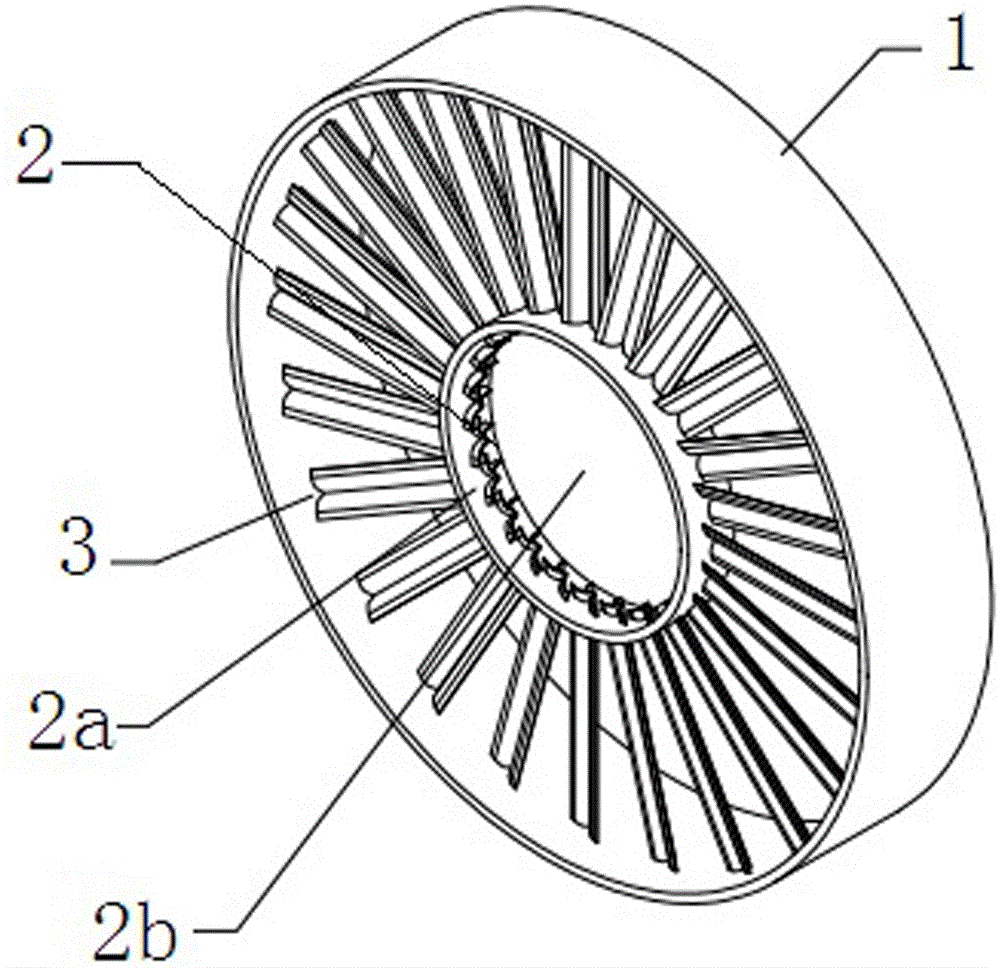
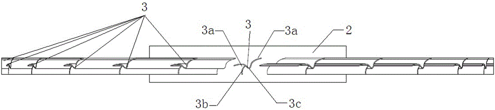
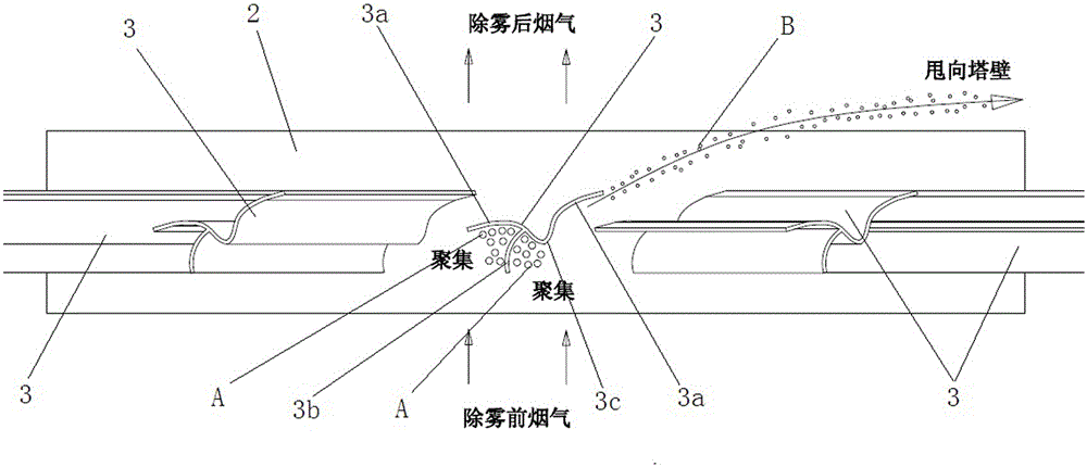
[0017] As shown in the figure, the present invention includes a support ring 1, a support shaft 2 located in the middle of the support ring 1, and several blades 3 distributed around the support shaft 2 and welded and fixed between the support ring 1 and the support shaft 2. The blades 3 include Two connected blade units 3a with a convex arc-shaped cross section and a hook blade 3b bent outward and downward fixedly connected to one of the blade units 3a by welding, and the blade 3 is connected along one of the blade units with the hook blade 3b The direction from 3a to the other blade unit 3a is inclined upward.
[0018] The support shaft 2 includes a cylinder 2a and a blind plate 2b that closes the through hole in the middle of the cylinder 2a.
[0019] The connecting part of the two blade units 3a is a bending part 3c, and the two blade units 3a together with the bending part 3c are integrally formed by bending a stainless steel plate.
[0020] Such as image 3 As shown, in the process of removing the flue gas from the mist eliminator blades, the particles A with larger particle size are intercepted and gathered by the hook blade 3b on the blade 3 and the upper convex arc structure of the blade unit 3a where the hook blade 3b is located. When it reaches a certain amount, it can be washed clean by flushing water; particles B with a smaller particle size cannot be intercepted by the hook blade 3b and the blade unit 3a where the hook blade 3b is located, and flow out in a swirling flow along the blade 3 with the smoke. Due to the high density of small particles B, they are thrown to the tower wall and adhered and aggregated, while the smoke with less density continues to rise, achieving the purpose of simultaneous removal of small particles and large particles.

PUM

no PUM

Description & Claims & Application Information

We can also present the details of the Description, Claims and Application information to help users get a comprehensive understanding of the technical details of the patent, such as background art, summary of invention, brief description of drawings, description of embodiments, and other original content. On the other hand, users can also determine the specific scope of protection of the technology through the list of claims; as well as understand the changes in the life cycle of the technology with the presentation of the patent timeline. Login to view more.

Similar technology patents

External shell-and-tube heat exchanger and design method thereof

ActiveCN110274495ALittle resistance lossThe velocity gradient of the flow field decreases
Owner:CHINA SHIP SCIENTIFIC RESEARCH CENTER (THE 702 INSTITUTE OF CHINA SHIPBUILDING INDUSTRY CORPORATION)

Novel furnace for recovering waste heat to generate power

PendingCN111076218AGood energy saving effectLittle resistance loss
Owner:YANTAI UNIV

Silent type multifunctional micro-resistance water pump control valve

InactiveCN104455610ALittle resistance lossSmall flow resistance
Owner:高仁超

Constant-temperature dehumidification and refrigeration device

PendingCN111970911ALittle resistance lossavoid shock
Owner:陶冬梅

Classification and recommendation of technical efficacy words

  • reduce in quantity
  • Little resistance loss

Assembly concrete new type pillar and beam structure and assembly connecting method

InactiveCN104727439Areduce in quantityReliable connection force transmission
Owner:SHENYANG JIANZHU UNIVERSITY

Film bulk acoustic resonator having multiple resonance modes and preparation method thereof and filter

ActiveCN105897211Areduce in quantityReduce the difficulty of production
Owner:SOUTH CHINA UNIV OF TECH

Filter self-cleaning system

InactiveCN103405960ALittle resistance lossImprove operational efficiency
Owner:CHINA RAILWAY SIYUAN SURVEY & DESIGN GRP

Pulse tube refrigerator and flow guide structure thereof

ActiveCN105042922ALittle resistance lossImprove the diversion effect
Owner:TECHNICAL INST OF PHYSICS & CHEMISTRY - CHINESE ACAD OF SCI

Cylinder head bypass backflow type piston compressor gas amount stepless adjustment method

ActiveCN109653982ALittle resistance lossSignificant reduction in energy consumption
Owner:BEIJING UNIV OF CHEM TECH

External shell-and-tube heat exchanger and design method thereof

ActiveCN110274495ALittle resistance lossThe velocity gradient of the flow field decreases
Owner:CHINA SHIP SCIENTIFIC RESEARCH CENTER (THE 702 INSTITUTE OF CHINA SHIPBUILDING INDUSTRY CORPORATION)
Why Eureka
Try Eureka