
Ultrasonic flowmeter with plugging positioning function

An ultrasonic and flowmeter technology, used in the measurement of flow/mass flow, liquid/fluid solid measurement, and measurement devices, etc., can solve the problems of inaccurate positioning, increase production costs, and measure medium leakage, and achieve high measurement accuracy and fixed Reliable, quick disassembly and assembly

Active Publication Date: 2015-11-11
WEIHAI PLOUMETER
View PDF5 Cites 7 Cited by
  • Summary
  • Abstract
  • Description
  • Claims
  • Application Information

AI Technical Summary

Problems solved by technology

[0002] As we all know, the existing ultrasonic flowmeter is composed of a flow tube body, a measuring tube body, a transducer mounting tube body, a positioning element, a reflector mount, a reflector and a transducer. The side wall of the flow tube body is provided with Two transducer installation pipes and positioning holes, the flow pipe body is provided with a measuring pipe body, the transducer installation pipe body communicates with the flow pipe body, and the flow pipe body is connected to the measurement pipe body through the positioning element Phase is fixed, the transducer body is provided with a transducer, the two ends of the measuring tube are respectively equipped with reflector mounts, and reflectors are arranged on the reflector mounts, and the reflector and transducer Correspondingly, the shortcomings of this structure are: 1. Due to the small diameter of the positioning element, the positioning is not accurate enough. Under the repeated impact of the water flow, the positioning of the mirror mounting seat in the measuring pipe section is unreliable
2. Both the flow pipe body and the measuring pipe section need to process positioning holes, which increases the production cost and adds a leakage point at the same time. There is a hidden danger of leakage of the measurement medium during use.

Method used


Image

  • Ultrasonic flowmeter with plugging positioning function
  • Ultrasonic flowmeter with plugging positioning function
  • Ultrasonic flowmeter with plugging positioning function

Examples


Embodiment Construction

[0016] Below in conjunction with accompanying drawing, the present invention is further described:

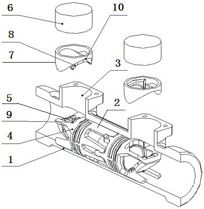
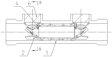
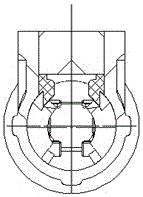
[0017] As shown in the drawings, an ultrasonic flowmeter with plug-in positioning includes a flow pipe body 1, a measuring pipe body 2, a transducer mounting pipe body 3, a reflector mounting seat 4, a reflector 5 and a transducer 6 , the flow pipe body 1, the measuring pipe body 2, the transducer installation pipe body 3, the reflector mounting seat 4, the reflector 5 and the transducer 6 are connected in the same relationship as the prior art, which will not be described in detail here. A positioning sleeve 7 is provided between the flow pipe body 1 and the reflector mounting seat 4, the positioning sleeve 7 is cylindrical, the center of the positioning sleeve 7 is provided with an ultrasonic channel, and the lower end of the positioning sleeve 7 is provided with a positioning insert 8, The positioning insert 8 extends axially along the lower end of the positioning sleeve 7 t...


PUM


Abstract

The invention discloses an ultrasonic flowmeter with a plugging positioning function. The ultrasonic flowmeter comprises a flow tube body, a measuring tube body, a transducer mounting tube body, a reflector mounting seat, a reflector and a transducer. The ultrasonic flowmeter is characterized in that a positioning sleeve is arranged between the flow tube body and the reflector mounting seat; the positioning sleeve is cylindrical; the center of the positioning sleeve is provided with an ultrasonic channel; the lower end of the positioning sleeve is provided with a positioning inserter; the positioning inserter axially extends along the lower end of the positioning sleeve, thereby facilitating positioning the positioning sleeve onto the reflector mounting seat; the sidewall of the reflector mounting seat is provided with a positioning slot; the positioning inserter matches the positioning slot; the upper end of the positioning sleeve is closely inserted into the transducer mounting tube body and contacts with the transducer; and the lower end is plugged with the positioning slot of the reflector mounting seat for positioning through the positioning inserter. The ultrasonic flowmeter has advantages of novel structure, quick detachment, high positioning accuracy, high fixation reliability, high measurement accuracy, etc.

Description

technical field [0001] The invention relates to the technical field of flow measurement, in particular to an ultrasonic flowmeter with plug-in positioning. Background technique [0002] As we all know, the existing ultrasonic flowmeter is composed of a flow tube body, a measuring tube body, a transducer mounting tube body, a positioning element, a reflector mount, a reflector and a transducer. The side wall of the flow tube body is provided with Two transducer installation pipes and positioning holes, the flow pipe body is provided with a measuring pipe body, the transducer installation pipe body communicates with the flow pipe body, and the flow pipe body is connected to the measurement pipe body through the positioning element Phase is fixed, the transducer body is provided with a transducer, the two ends of the measuring tube are respectively equipped with reflector mounts, and reflectors are arranged on the reflector mounts, and the reflector and transducer Correspondin...

Claims


Application Information

Patent Timeline
IPC IPC(8): G01F1/66
Inventor 付涛戚清门建青
Owner WEIHAI PLOUMETER
Learn More