Long tail wave impulse current generator

A technology of impulse current generation and long tail, applied in the direction of measuring devices, measuring electricity, measuring electrical variables, etc., can solve problems such as difficulty in debugging waveforms, difficult coordination, and discharge failure, so as to reduce the test failure rate and improve the utilization rate of capacitors , The effect of high waveform output efficiency

Active Publication Date: 2018-06-12
SUZHOU 3CTEST ELECTRONIC CO LTD
View PDF7 Cites 0 Cited by
  • Summary
  • Abstract
  • Description
  • Claims
  • Application Information

AI Technical Summary

Problems solved by technology

[0006] (1) The control of the generator is more complicated, and it is necessary to control the trigger system of two sets of generators (the long-tail wave impulse current generator and the impulse voltage generator) at the same time, so that the impulse voltage generator can delay the impulse current for a certain period of time. The control must be accurate, otherwise it is prone to discharge failure and the control is difficult;
[0007] (2) For multiple ball distance control, the whole system needs to control the three-ball motion of G2 and the coupling ball gap of G3, as well as the trigger ball gap of the impulse voltage generator body, in addition to this set of triggers, which is difficult to coordinate;
[0008] (3) It is difficult to debug the waveform. The length of the wave tail is controlled by the size of the crowbar energy storage inductor L1, but the load impedance of different tested products is different, resulting in large fluctuations in the duration of the wave tail

Method used


Image

  • Long tail wave impulse current generator
  • Long tail wave impulse current generator
  • Long tail wave impulse current generator

Examples


Embodiment

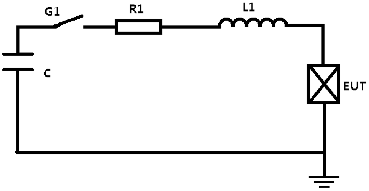
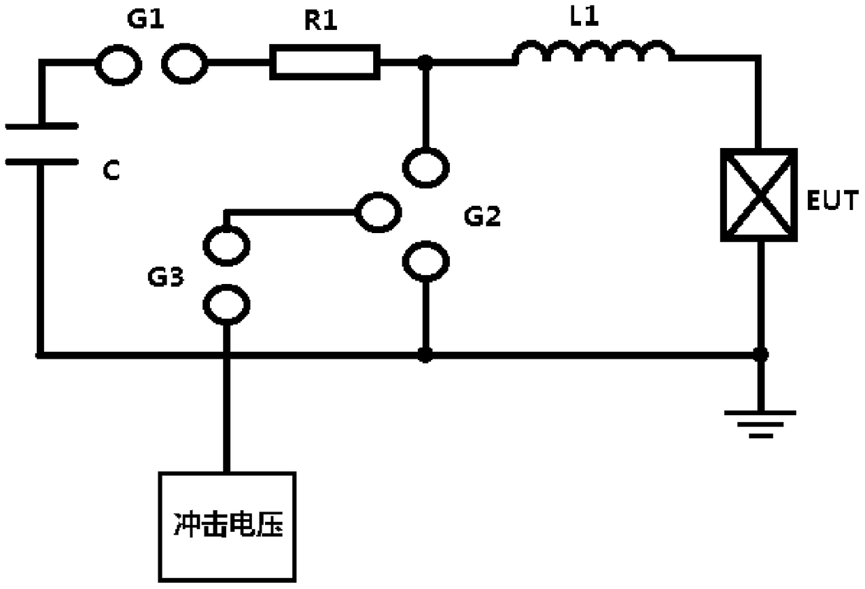
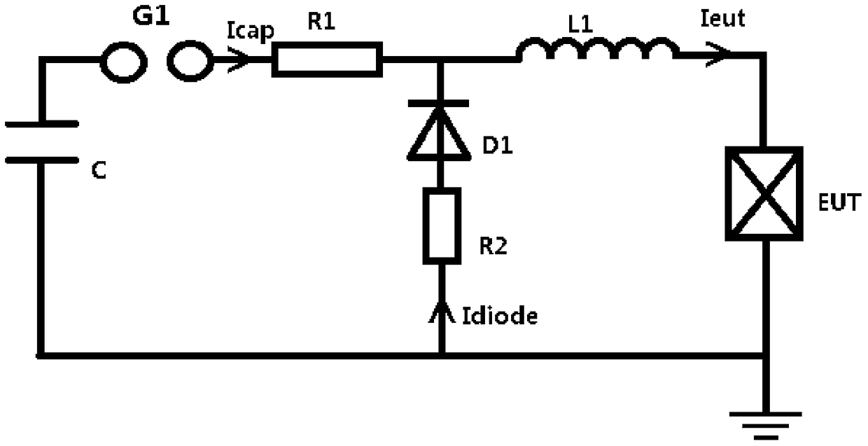
[0040]Embodiment: A long-tail shock current generating device, including a charging unit 1, an energy storage unit 2, a gap switch unit 3, at least one first modulation resistor 4, a second modulation resistor 5, an inductor 6, and a non-gap type An adaptive crowbar switch unit 7 and a test object carrier 8, the charging unit 1 is connected to the energy storage unit 2, the non-gap adaptive crowbar switch unit 7 in series, and the second wave modulation resistor 5 are connected in parallel with the energy storage unit 2 And it is located between the inductance 6 and the gap switch unit 3 connected in series and the first modulation resistor 4;

[0041] Described gap switch unit 3 comprises the high-voltage capacitor side conductive disk 9, the high-voltage inductance side conductive disk 10 and the low-voltage conductive disk 11 arranged at intervals, the high-voltage capacitor side conductive disk 9, the high-voltage inductance side conductive disk 10 and the low-voltage condu...


PUM


Abstract

The invention discloses a long-tail wave impulse current generation device comprising a charging unit, an energy storage unit, a gap switch unit, at least one first wave-modulated resistor, a second wave-modulated resistor, an inductor, a non-gap adaptive Crowbar switch unit, and a carrier for to-be-tested objects. The charging unit is connected to the energy storage unit. The non-gap adaptive Crowbar switch unit and the second wave-modulated resistor, which are connected in series, are connected in parallel with the energy storage unit and are disposed between the inductor on one hand and the gap switch unit and the at least one first wave-modulated resistor which are connected in series on the other hand. The non-gap adaptive Crowbar switch unit includes a high-voltage fast pulse semiconductor assembly and a support frame. A positioning mechanism is arranged at one end of a reversing rotation shaft, and the reversing rotation shaft is correspondingly provided with a positioning hole. The positioning mechanism includes a fixed block with a through hole, and an elastic pin installed in the through hole. Long-tail waveform can be output at low capacitance. Long-tail impact current wave as well as A wave and D wave of direct lightning waveform are realized. The utilization efficiency of capacitance is improved.

Description

technical field [0001] The invention relates to the technical field of surge protector testing, in particular to a long-tail shock current generator. Background technique [0002] Lightning is a natural discharge phenomenon in nature. After lightning occurs, through the action of electrostatic induction and electromagnetic induction, lightning overvoltage will be formed in the communication line. The long-coda impulse current generating device is mainly used in the generator of simulating lightning current to generate a pulse current waveform with large current and long duration, mainly used to simulate the current waveform of Class I lightning (direct lightning) 10 / 350μs, and the direct lightning effect of aircraft Generator for test waveform A component, D component, and power supply 10 / 1000μs long wave tail waveform. [0003] At present, there are two main types of long-tail shock current generators on the market, one is the CRL discharge circuit based on traditional te...

Claims


Application Information

Patent Timeline
Patent Type & Authority Patents(China)
IPC IPC(8): G01R1/28
Inventor 赵涛宁黄学军蔡省洋王娇张毅
Owner SUZHOU 3CTEST ELECTRONIC CO LTD
Why Eureka
Try Eureka