thermal protector

A protector, over-temperature technology, applied in protection switches, emergency protection devices, parts of protection switches, etc., can solve the problems of over-temperature protectors being large in size and being easily affected by external forces, avoiding instantaneous disconnection of vibration, eliminating The effect of reducing the number of transmission links and parts

Active Publication Date: 2018-01-16
上海神沃电子有限公司
View PDF5 Cites 0 Cited by
  • Summary
  • Abstract
  • Description
  • Claims
  • Application Information

AI Technical Summary

Problems solved by technology

[0013] In view of the above-mentioned shortcomings of the prior art, the purpose of the present invention is to provide an over-temperature protector, which changes the stacked structure in the prior art into a planar distribution structure, and changes the elastic switch into a plug-in switch, which is used for Solve the problems of large volume and easy to be affected by external force in the prior art

Method used


Image

  • thermal protector
  • thermal protector
  • thermal protector

Examples


Embodiment 1

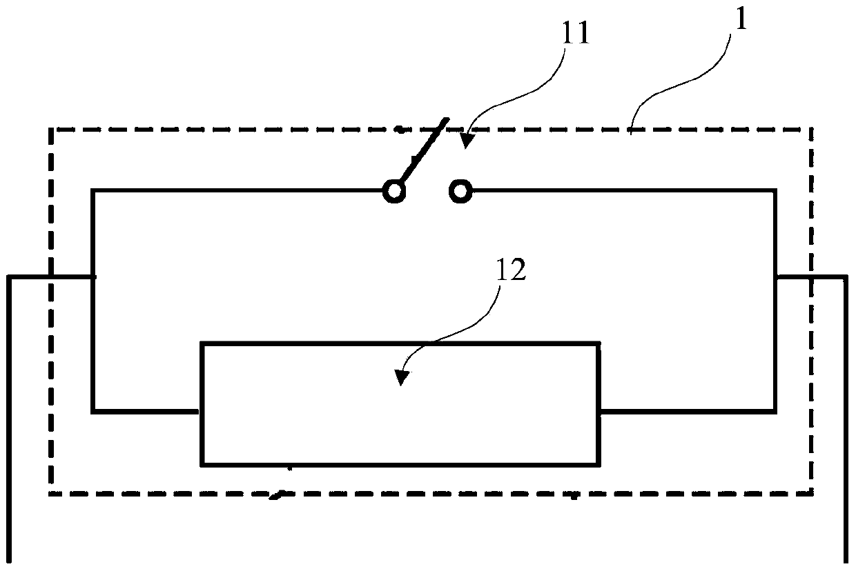
[0067] Such as figure 2 As shown, the working circuit 1 of the over-temperature protector of the present invention adopts a mode in which a heat-driven switch 11 and a heating element 12 are connected in parallel. Wherein the heat-actuated switch is made of temperature-sensitive material, the heat-actuated switch is closed under normal temperature state, and the heat-actuated switch is opened under high temperature state. The thermally actuated switch can change rapidly within the set temperature range, and complete the shape change to realize the circuit opening and closing. The heating element continues to generate heat after the drive switch cuts off the circuit, and the heat emitted by it prevents the heat drive switch from closing.

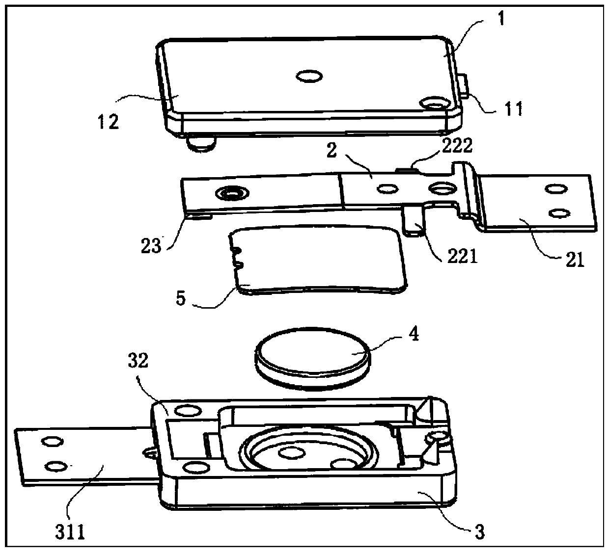
[0068] Such as Figure 2 to Figure 8 As shown, this embodiment provides an over-temperature protector, the over-temperature protector includes a heating element, a driving arm, a first contact structure, and a second contact structure, and...

Embodiment 2

[0079] Such as Figure 9 ~ Figure 14 As shown, this embodiment provides an over-temperature protector, the basic working principle and basic structure of the over-temperature protector are as in embodiment 1, wherein, compared with embodiment 1, the improvement is that the driving arm is embedded and fixed In this way, it is more beneficial to improve the heat transfer efficiency of PPTC to the driving arm and the structural strength of the fixing of the driving arm.

Embodiment 3

[0081] Such as Figure 15 ~ Figure 16 As shown, this embodiment provides an over-temperature protector, the basic working principle and basic structure of the over-temperature protector are as in embodiment 2, wherein, compared with embodiment 2, the improvement is that the heating element groove 33 The geometric design with the driving arm slot 34 is more beneficial to improve the heat transfer efficiency of the PPTC to the driving arm and provide the driving arm with a certain range of motion.

[0082] Such as Figure 15 As shown, the over-temperature protector restricts the driving arm slot 34 so that the driving arm will not deform too much when the external temperature fluctuates greatly, thereby limiting the movable range of the driving arm, causing damage to the placement structure and reducing sensitivity.

[0083] Such as Figure 16 As shown, the overtemperature protector combines the heating element groove 33 and the driving arm groove 34 into one to form an overal...


PUM


Abstract

The invention provides an over-temperature protector comprising a heating element, a driving arm, a first contact structure, and a second contact structure. A first circuit is formed by the heating element, the first contact structure, and the second contact structure. A second circuit in parallel with the first circuit is formed by the driving arm, the first contact structure, and the second contact structure. The driving arm is deformed under thermal driving in order to be in an on-state or off-state with the second circuit. The over-temperature protector integrates a driving part and a switch part into one body, eliminates a transmission link, decreases the number of components, reduces production cost, and facilitates processing and manufacture. A flexural and deformable driving switch thins the protector while guaranteeing motion distance. A plug-in switch fundamentally prevents a possibility of vibration momentary open circuit due to elastic contact. The over-temperature protector is simple in structure and has wide application prospect in the field of circuit protectors.

Description

technical field [0001] The invention relates to a circuit protection device, in particular to an over-temperature protector with a planar structure and a plug-in switch. Background technique [0002] There are many kinds of circuit breakers with thermal protection function on the market: including bimetal thermal protector, PTC thermal protector, Breaker thermal protector, electronic circuit type thermal protector, etc. [0003] Among them, the Breaker type thermal protector combines the common advantages of bimetal and PTC. For example, in the patent application "A Thin Circuit Protection Device" (Application No. 201310703359.0), a typical breaker thermal protection element is disclosed, and its specific structure is as follows figure 1 As shown, the structure is designed to have a small volume, a typical stacked structure, and an arm-type elastic switch. However, the use of elastic switches cannot avoid the impact of external impacts, and the stacked structure also limit...

Claims


Application Information

Patent Timeline
Patent Type & Authority Patents(China)
IPC IPC(8): H01H71/16H01H71/14
CPCH01H71/14H01H71/164
Inventor 赵亮侯李明唐佳林符林祥臧育锋
Owner 上海神沃电子有限公司
Why Eureka
Try Eureka