
Self-correction starting method based on rotor position detection for brushless motor

A rotor position, brushless motor technology, applied in the direction of electronic commutator, starting device, etc., can solve problems such as failure to start, wrong determination of rotor position, etc.

Active Publication Date: 2015-11-11
无锡雷利电子控制技术有限公司 +1
View PDF4 Cites 0 Cited by
  • Summary
  • Abstract
  • Description
  • Claims
  • Application Information

AI Technical Summary

Problems solved by technology

If it is determined that the initial position is wrong, the controller can automatically correct the phase of the rotor according to the phase of the input voltage, so as to drive the motor correctly, which solves the problem that the single-phase brushless motor cannot be started due to the wrong determination of the rotor position when starting in the prior art

Method used


Image

  • Self-correction starting method based on rotor position detection for brushless motor
  • Self-correction starting method based on rotor position detection for brushless motor
  • Self-correction starting method based on rotor position detection for brushless motor

Examples


Embodiment Construction

[0039] The present invention will now be described in detail with reference to the accompanying drawings. The present invention is described by taking a single-phase brushless motor as an example to make the principle of the present invention easy to understand, but the description by taking a single-phase brushless motor as an example does not limit the practical application scope of the present invention to single-phase brushless motors. For motors, the method of the present invention is also applicable to multi-phase brushless motors, and multi-phase brushless motors are also within the scope of the present invention.

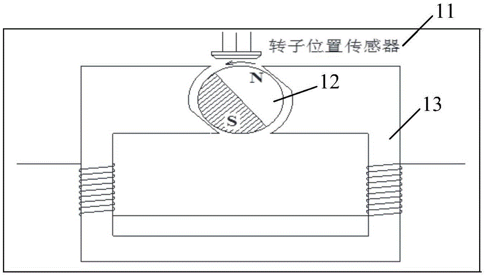
[0040] figure 1 A block diagram showing the internal structure of a single-phase brushless motor. Such as figure 1 As shown, the single-phase brushless motor generally consists of an electronic control system (not shown), a rotor position sensor 11 , a rotor 12 and a stator 13 in structure.

[0041] The rotor position sensor 11 can usually choose a magnet...


PUM


Abstract

A self-correction starting method based on rotor position detection for a brushless motor by using a single Hall sensor to detect rotor position comprises the following steps of: reading initial voltage waveform detected by a rotor position sensor before the motor starts; setting a rotor position state variable as a first state or a second state according to a comparison result between the initial voltage waveform and a first threshold value; carrying out a maximum value detection process of the rotor position sensor if the rotor position state variable is the first state; carrying out a minimum value detection process if the rotor position state variable is the second state; and finishing the self-correction starting method if the maximum value detection process and the minimum value detection process of the rotor position sensor are completed.

Description

technical field [0001] The invention belongs to the field of brushless motor control, and in particular relates to a self-correcting starting method of a brushless motor based on detecting the position of a rotor by a single Hall sensor. Background technique [0002] In recent years, with the development of permanent magnet new materials, microelectronics technology, automatic control technology and power electronics technology, especially high-power switching devices, brushless motors have made great progress. Among them, the detection of the rotor position of the motor is correct and reliable, which plays a very critical role in shortening the starting time of the motor and increasing the success rate of starting the motor. [0003] However, due to the installation position of the sensor, the strength of the rotor magnetic field and the level of production technology all affect the detection accuracy of the rotor position, errors in the detection feedback signal are unavoi...

Claims


Application Information

Patent Timeline
IPC IPC(8): H02P6/20H02P6/16
Inventor 王明仁刘猛王胜
Owner 无锡雷利电子控制技术有限公司
Learn More