
High voltage direct current (HVDC) converter system and method of operating the same

A high-voltage direct current and converter technology, applied in the direction of output power conversion device, conversion of AC power input to DC power output, power transmission AC network, etc.

Inactive Publication Date: 2015-11-11
GENERAL ELECTRIC CO
View PDF5 Cites 6 Cited by
  • Summary
  • Abstract
  • Description
  • Claims
  • Application Information

AI Technical Summary

Problems solved by technology

Furthermore, for those conditions that include transients or faults on either the AC side or the DC side of a thyristor-based rectifier, interruption of power commutation can result in

Method used


Image

  • High voltage direct current (HVDC) converter system and method of operating the same
  • High voltage direct current (HVDC) converter system and method of operating the same
  • High voltage direct current (HVDC) converter system and method of operating the same

Examples


Embodiment Construction

[0021] In the following specification and claims, reference will be made to various terms defined to have the following meanings.

[0022] The singular forms "a", "an", "the" and "said" include plural references unless the context clearly dictates otherwise.

[0023] "Optional" or "optionally" means that the subsequently described event or circumstance can or cannot occur, and that the description includes instances where the event occurs and instances where it does not.

[0024] Approximate language as used herein may be employed throughout the specification and claims to modify any quantitative representation that permissible changes do not result in a change in the basic function to which it is related. Accordingly, a value modified by a term or terms such as "about" and "substantially" is not to be limited to the precise value specified. In at least some cases, the approximate language may correspond to the accuracy of the instrument used to measure the value. Here and t...


PUM


Abstract

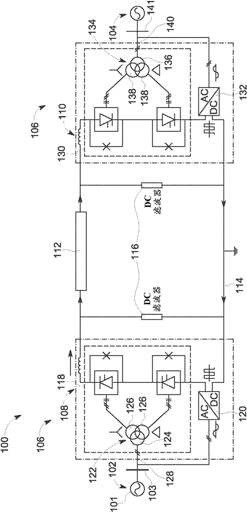
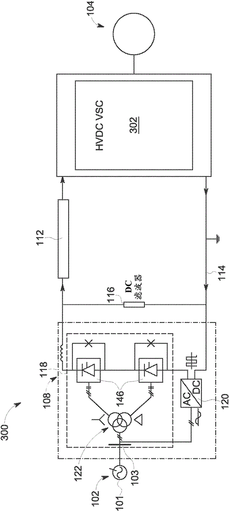
A high voltage direct current (HVDC) converter system includes at least one line commutated converter (LCC) and at least one current controlled converter (CCC). The at least one LCC and the at least one CCC are coupled in parallel to at least one alternating current (AC) conduit and are coupled in series to at least one direct current (DC) conduit. The at least one LCC is configured to convert a plurality of AC voltages and currents to a regulated DC voltage of one of positive and negative polarity and a DC current transmitted in only one direction. The at least one current controlled converter (CCC) is configured to convert a plurality of AC voltages and currents to a regulated DC voltage of one of positive and negative polarity and a DC current transmitted in one of two directions.

Description

[0001] Statement on Federal Funding for Research and Development [0002] This invention was made with Government support under Contract No. DE-AR0000224 awarded by the Advanced Research Projects Agency-Energy (ARPA-E). The Government may have certain rights in this invention. technical field [0003] The field of the invention relates generally to high voltage direct current (HVDC) transmission systems, and more particularly to HVDC converter systems and methods of operation thereof. Background technique [0004] It is known that at least a portion of power generation facilities are physically located in remote geographic areas or areas where physical access is difficult. One example includes power generation facilities that are geographically located in rugged and / or remote areas, such as mountainous terrain, and offshore, such as offshore wind turbine installations, at extended distances from consumers. More specifically, the wind turbines may be physically co-located i...

Claims


Application Information

Patent Timeline
Patent Type & Authority Applications(China)
IPC IPC(8): H02M7/757H02J3/36
CPCH02J3/36H02M7/7575Y02E60/60H02M1/0095
Inventor R.K.古普塔N.R.乔扈里
Owner GENERAL ELECTRIC CO
Learn More